Are you searching for a plastic material that resists aggressive chemicals, survives extreme temperatures from -200°C to +150°C, and lasts decades outdoors — yet can still be injection molded into complex, precision geometries without switching to exotic manufacturing processes?
ETFE plastic sits at that rare intersection: a fluoropolymer with the chemical resistance of PTFE, the mechanical strength twice that of PTFE, genuine optical transparency, and the ability to be injection molded into complex geometries. From the iconic bubble façade of Beijing’s Water Cube to the high-purity fluid components inside semiconductor wet-process equipment, ETFE plastic material has earned its place as one of the most versatile and high-value engineering polymers available today. This guide covers everything you need to know — ETFE properties and specifications, injection molding process parameters, a detailed ETFE vs PTFE comparison, application scenarios where ETFE excels (and where it does not), and practical guidance on working with a precision injection molding partner to bring your ETFE parts from design to production.
What is ETFE plastic?
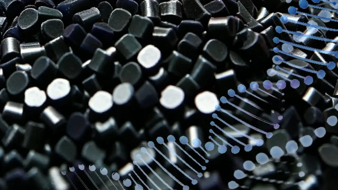
ETFE plastic, whose full name is ethylene-tetrafluoroethylene copolymer (Ethylene Tetrafluoroethylene), is a semi-crystalline fluoropolymer thermoplastic material synthesized through a copolymerization reaction between ethylene and tetrafluoroethylene (TFE). Its CAS number is 25038-71-5, and its chemical formula can be represented as –(CH₂CH₂)ₓ–(CF₂CF₂)ₙ–.
Unlike fully fluorinated PTFE (polytetrafluoroethylene), ETFE incorporates ethylene units into its molecular chain, allowing it to retain the excellent chemical resistance and wide-temperature-range stability characteristic of the fluoropolymer family, while significantly improving mechanical toughness, processability, and optical transparency. Commercially, the best-known brand of ETFE plastic is Tefzel® from DuPont; other notable brands include Solvay’s Hyflon® ETFE and AGC’s Fluon® ETFE series.
From the perspective of injection molding engineers, ETFE has several key characteristics that warrant special attention:
It is a true thermoplastic material that can be processed using standard injection molding equipment, which is a fundamental difference from PTFE—since PTFE cannot melt and flow, it is typically only suitable for compression sintering;
ETFE has a melting point of approximately 267°C, and its processing window is more demanding than that of most engineering plastics, requiring specialized equipment and process control;
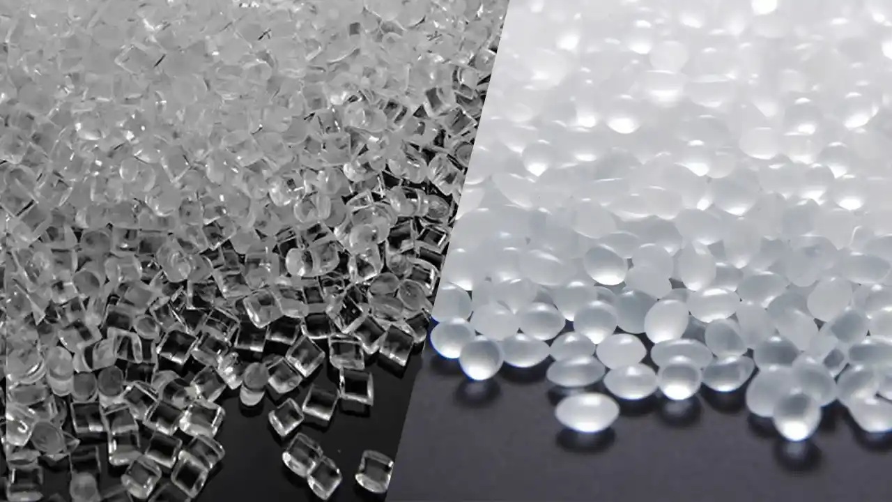
ETFE possesses a unique semi-translucent to transparent appearance, which is extremely rare among fluoropolymers, giving it irreplaceable application value in the architectural, optical, and solar energy sectors.
In terms of market positioning, ETFE plastic occupies the intersection between “high-performance engineering plastics” and “specialty fluoropolymers”—its performance far exceeds that of general-purpose engineering plastics such as ABS, PP, and PA, yet compared to extremely heat-resistant materials like PEEK and PPS, it offers lower processing temperatures, better flow properties, and more competitive material costs. For applications requiring chemical resistance, a wide temperature range, excellent mechanical properties, and a certain degree of transparency, ETFE is often the optimal or only solution.
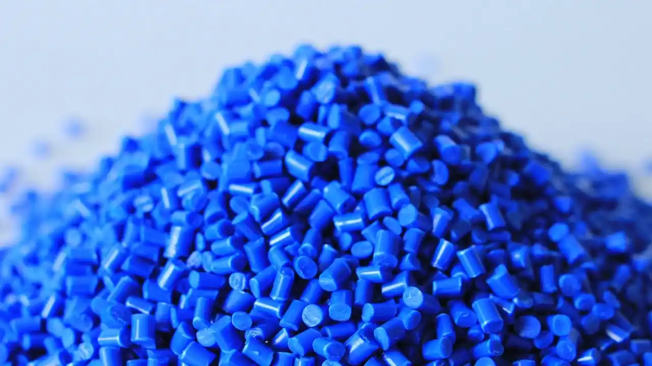
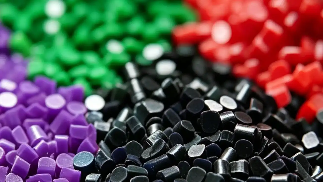
In the Dimud injection molding material database, ETFE is classified under the “Specialty High-Performance Fluoropolymers” category. It belongs to a material system that is relatively difficult to process but offers significant added value, and is typically used in precision component projects for customers in Europe and North America across the chemical, electronics, medical, and new energy sectors.
The Chemical Structure and Molecular Mechanism of ETFE
To understand the application limits of ETFE plastic, one must start with its molecular structure. In ETFE molecular chains, the molar ratio of ethylene (E) to tetrafluoroethylene (TFE) is typically controlled between 40:60 and 60:40; for industrial-grade products, the optimal range is TFE:E = 65:35 to 50:50.
In addition to the main-chain monomers, industrially produced ETFE typically incorporates a third monomer (accounting for approximately 0.3–1.7 mol%) to regulate crystallinity, improve melt flow, and further enhance mechanical strength within specific temperature ranges.
Why introduce ethylene units?
The molecular chains of pure PTFE (fully fluorinated structure) consist solely of C–F bonds, which confer extremely high chemical inertness but also result in:
Extremely high melt viscosity, making it impossible to process via conventional injection molding or extrusion;
Relatively low tensile strength and impact resistance;
Significant light scattering, resulting in a white, opaque material;
In ETFE, however, the introduction of ethylene units creates C-H bonds, allowing the molecular chains to retain the chemical inertness of the fluorinated segments while gaining:
Lower melt viscosity and a wider processing window;
Higher tensile strength (more than double that of PTFE);
A combination of toughness and elasticity resulting from its semi-crystalline structure;
High transmittance of visible light and UV (up to 95%).
The Semi-Crystalline Nature of ETFE
ETFE plastic is a semi-crystalline polymer with a glass transition temperature (Tg) of approximately -100°C to -80°C and a melting point (Tm) of approximately 267°C. Its semi-crystalline structure confers two key engineering advantages on ETFE:
First, within the temperature range above Tg and well below Tm, ETFE combines the rigidity provided by crystalline regions with the toughness provided by amorphous regions. This is the physical basis for its stable mechanical properties across a wide temperature range of -200°C to +150°C; Second, during the injection molding process, the cooling rate directly affects crystallinity, which in turn influences shrinkage and dimensional stability—these are critical parameters that must be carefully considered in the design of ETFE injection molds.
ETFE Properties: A Detailed Explanation of Key Performance Parameters and Specifications
The following data is based on standard industrial-grade ETFE grades (such as the Tefzel® 200/210 series), with testing conducted in accordance with ASTM and ISO standards. Due to variations among different brands and modified grades, the technical data sheets (TDS) provided by the supplier should be used as the definitive reference for actual projects.
Mechanische Eigenschaften
| Performance Metrics | Typical value | Testing Standards |
|---|---|---|
| Tensile strength (23°C) | 40–50 MPa | ASTM D638 |
| Dehnung bei Bruch | 150–250% | ASTM D638 |
| Biegemodul | 800–1100 MPa | ASTM D790 |
| Notched impact strength (Izod) | 5–15 kJ/m²(23°C) | ASTM D256 |
| Hardness (Shore D) | 60–65 | ASTM D2240 |
| Compressive strength | 38–48 MPa | ASTM D695 |
ETFE has a tensile strength approximately 2 to 2.5 times that of PTFE, while maintaining good toughness and elongation at break. It is worth noting that ETFE properties remain excellent at low temperatures—even at liquid nitrogen temperatures (-196°C), the material retains considerable impact toughness and does not exhibit low-temperature brittle fracture, which is of significant value in cryogenic engineering and aerospace applications.
Thermal properties
| Performance Metrics | Typical value | Remark |
|---|---|---|
| Melting temperature (Tm) | 267°C | Semi-crystalline polymer |
| Maximum continuous service temperature | +150°C | Langfristige Stabilität |
| Extreme instantaneous temperature | +200°C | Bear in the short term |
| Low-temperature limit | -200°C | Does not become brittle |
| Heat Deflection Temperature (HDT, 1.82 MPa) | 104°C | ASTM D648 |
| Coefficient of Linear Thermal Expansion (CTE) | 8~12 × 10⁻⁵ /°C | Superior to general-purpose engineering plastics |
| Thermal Conductivity | 0.24 W/(m·K) | Low thermal conductivity, good thermal insulation |
The coefficient of thermal expansion of ETFE is significantly higher than that of metals and most engineering plastics (such as PEEK, which is approximately 4.7 × 10⁻⁵ /°C); therefore, when designing ETFE injection-molded parts that involve metal inserts or precision fits, it is essential to fully account for dimensional changes caused by temperature variations.
Elektrische Eigenschaften
| Performance Metrics | Typical value | Testing Standards |
|---|---|---|
| Durchschlagfestigkeit | 60~80 kV/mm | ASTM D149 |
| Volume Resistivity | > 10¹⁵ Ω·cm | ASTM D257 |
| Dielektrizitätskonstante (1 MHz) | 2.6 | ASTM D150 |
| Tangent of the dielectric loss angle (1 MHz) | < 0.001 | ASTM D150 |
| Flame Retardancy Rating | UL 94 V-0 | Selected Grades |
Its low dielectric constant and extremely low dielectric loss make ETFE plastic an ideal choice for the insulation of high-frequency signal transmission cables, and it is widely used in applications such as 5G base station cables and aviation wireless communications.
Chemische Beständigkeit
ETFE exhibits excellent resistance to most chemicals, but the following variations in performance should be noted:
Excellent Resistance (Virtually No Effect):
- Inorganic acids of all concentrations (hydrochloric acid, sulfuric acid, nitric acid, hydrofluoric acid)
- Alkaline solutions (NaOH, KOH, and other concentrations)
- Organic solvents (ketones, esters, alcohols)
- Halogen gases (chlorine, fluorine)
- Oxidizing agents (H₂O₂, concentrated nitric acid)
- Fuels and lubricants
Situations requiring caution:
Oleum may cause slow corrosion at high temperatures
Molten alkali metals (sodium, potassium)
Highly polar organic solvents at high temperatures
In comparison, ETFE exhibits greater chemical resistance than most engineering thermoplastics (such as PA, PBT, and ABS), but its stability in extreme oxidative environments is slightly inferior to that of fully fluorinated PTFE or PFA.
3.5 Optical and Transparency Properties
ETFE plastic offers unique optical advantages within the fluoropolymer family:
- Visible light transmittance: Up to 95% (comparable to high-quality glass)
- UV transmittance: Superior to ordinary glass, allowing transmission of UV light down to 240 nm
- Long-wave infrared transmittance: Good (a key indicator affecting plant photosynthesis in greenhouses)
- Refractive index: Approximately 1.40
These optical properties, combined with ETFE’s weather resistance and resistance to UV degradation, constitute the core competitive advantage of ETFE plastic panels und ETFE structures in architectural applications.
Machining Parameters
| parameter | Typical value |
|---|---|
| Melt Flow Rate (MFR, 297°C/5kg) | 4~40 g/10 min(Varies by grade) |
| Injection molding barrel temperature range | 290~330°C |
| Formtemperatur | 80~150°C |
| Einspritzdruck | 70~120 MPa |
| Shrinkage rate | 1.5%~3.0% |
| Drying requirements | Pre-drying required: 120°C for 4–6 hours. |
Changes in properties of filled modified grades
In industrial applications, virgin (unfilled) ETFE is often not the optimal choice. The following are common filling modification schemes and their effects on ETFE properties:
Glass fiber reinforcement (GF-ETFE):
Adding 15%–25% chopped glass fibers is the most common modification scheme, with the following primary effects:
- Flexural modulus increases to 2,500–4,000 MPa (a 3–4-fold increase compared to unfilled ETFE)
- Tensile strength increases to 60–80 MPa
- Molding shrinkage decreases to 0.8%–1.5%, and shrinkage rates in the flow direction and perpendicular direction become more consistent
- Heat deflection temperature increases to 130–145°C
- Drawbacks: Elongation at break decreases significantly (20–50%), reducing the material’s toughness; transparency is lost, resulting in a white or milky white appearance; chemical resistance decreases slightly (exposed glass fibers on the surface can act as pathways for medium penetration)
Carbon fiber reinforcement (CF-ETFE):
- Provides higher stiffness and thermal conductivity (beneficial for heat dissipation applications)
- Confers some electrical conductivity (suitable for antistatic applications)
- Cost is significantly higher than glass-fiber-modified grades
PTFE-filled (PTFE-blended ETFE):
- Significantly reduces the coefficient of friction (from approximately 0.4 to 0.15–0.25), improving wear resistance
- Suitable for sliding seals requiring both corrosion resistance and low friction
Molybdenum disulfide (MoS₂) filled:
- Further improves lubricity
- Typically added in combination with PTFE
Carbon Black Filled (Conductive/Antistatic ETFE):
- Reduces volume resistivity from >10¹⁵ Ω·cm to 10⁴–10⁹ Ω·cm (antistatic grade) or <10⁴ Ω·cm (conductive grade)
- Widely used in antistatic piping for semiconductor cleanroom equipment and flammable liquid transfer systems
Dimud Engineering Recommendation: When initiating an ETFE injection molding project, grade selection should be treated as a separate engineering decision step. Selecting the wrong grade—such as using an unfilled grade for structural parts that require high modulus—may result in unexpected deformation or even failure of the parts during use. If you need technical support, the Dimud engineering team can provide professional grade recommendations and comparative testing plans tailored to your specific application.
Comprehensive Comparison of ETFE with Other High-Performance Engineering Plastics
To help engineers make more informed decisions during the material selection phase, the following is a comprehensive comparison of ETFE plastic with several common high-performance engineering plastics:
| Comparison dimensions | ETFE | PEEK | PPS | FEP | PFA |
|---|---|---|---|---|---|
| Kontinuierliche Betriebstemperatur | +150°C | +250°C | +220°C | +200°C | +260°C |
| Zugfestigkeit | 40~50 MPa | 100 MPa | 65~85 MPa | 20~25 MPa | 30~35 MPa |
| Coefficient of friction | 0.4 | 0.35 | 0.3 | 0.2 | 0.2 |
| Typical application overlap areas | Chemical Engineering, Electrical Engineering, and Construction | Medical and aerospace structural components | Automotive, high-temperature electronics | Cables, thin-walled chemical components | Ultra-high purity chemical equipment |
This comparison highlights ETFE’s unique positioning regarding specific performance attributes: it is one of the few known materials that simultaneously offers high transparency, injection moldability, stability across a wide temperature range, and comprehensive chemical resistance. While PEEK boasts superior mechanical properties, it lacks transparency and its chemical resistance is inferior to ETFE’s in certain solvent environments; FEP and PFA exhibit even greater chemical inertness but possess lower tensile strength, and their visible light transmission characteristics—critical for architectural and optical applications—do not match those of ETFE.
Advantages and Limitations of ETFE Plastic Material
Core Advantages
① Stability Across a Wide Temperature Range
ETFE material maintains stable mechanical and electrical properties across an extremely wide temperature range of -200°C to +150°C. This is its core competitive advantage that sets it apart from nearly all general-purpose engineering plastics. At temperatures where materials such as PA66 and PBT begin to soften and fail, ETFE retains its structural integrity; even at liquid nitrogen temperatures, it does not suffer from low-temperature brittle fracture like PC or ABS.
② Exceptional Chemical Inertness
It exhibits excellent resistance to virtually all inorganic acids, alkalis, and organic solvents, making it particularly suitable for applications involving contact with corrosive media, such as linings for chemical processing equipment, pump and valve components, and laboratory consumables.
③ Superior Weather Resistance and UV Degradation Resistance
ETFE is highly resistant to UV radiation, ozone, and industrial pollutants. It has a service life of 30 to 50 years or more when used outdoors, without significant yellowing, cracking, or deterioration in mechanical properties. This characteristic makes it the material of choice for large-scale architectural cladding and solar energy facilities.
④ A Truly Injection-Moldable Fluoropolymer
ETFE’s melt flow properties allow it to be processed using standard injection molding machines, enabling the manufacture of precision parts with complex three-dimensional geometries—a feat that PTFE cannot achieve through traditional injection molding processes. This characteristic significantly expands the application boundaries of fluoropolymers in the field of precision component manufacturing.
⑤ High Transparency and Excellent Optical Properties
Unique among fluoropolymers, ETFE achieves a visible light transmittance of up to 95% while maintaining good transmittance of UV and long-wave radiation, making it indispensable in architectural daylighting, solar energy, and medical optics.
⑥ Self-Cleaning Properties and Low Surface Energy
ETFE has extremely low surface energy (approximately 18 mN/m), making it difficult for dirt and grease to adhere. It can be self-cleaned simply by rainwater runoff, significantly reducing maintenance costs for large architectural structures.
⑦ Good Radiation Resistance
ETFE exhibits superior resistance to gamma radiation compared to PTFE, giving it an advantage in the nuclear industry, medical radiation equipment, and aerospace applications.
⑧ 100% Recyclable
As a thermoplastic material, ETFE can be completely melted down and reprocessed at the end of its service life, meeting the increasingly stringent circular economy requirements of current European and North American markets.
Limitations
① High Processing Costs
The price of raw materials is significantly higher than that of general-purpose materials such as ABS, PP, and PA—typically 10 to 30 times that of common engineering plastics. Additionally, injection molding requires corrosion-resistant equipment (as ETFE releases trace amounts of fluorinated gases when melted, which are corrosive to metal components), increasing equipment investment and maintenance costs.
② Narrow Injection Molding Process Window
Processing temperatures are high (barrel temperature 290–330°C), and extremely precise temperature control is required. Excessive temperatures can cause ETFE to decompose and produce HF (hydrofluoric acid) gas, posing a threat to equipment and operator safety; conversely, temperatures that are too low can result in insufficient mold filling or excessively deep weld lines. This requires injection molding equipment to have precise temperature control capabilities and the operating team to possess extensive experience in fluoropolymer processing.
③ Rapid mold wear
ETFE’s high processing temperatures and chemical reactivity are corrosive to mold steel, typically requiring the use of stainless steel or molds with special coatings (such as TiN), which increases mold manufacturing costs.
④ High and Anisotropic Shrinkage
Injection molding shrinkage ranges from 1.5% to 3.0%. Furthermore, crystalline orientation causes differences in shrinkage rates between the flow direction and the perpendicular direction, making dimensional accuracy control more difficult and placing higher demands on mold design and process parameter optimization.
⑤ Relatively Low Surface Hardness
Compared to metals and certain high-hardness engineering plastics (such as PEEK), ETFE has a lower surface hardness (approximately 60–65 on the Shore D scale) and exhibits inferior scratch resistance to these materials under conditions of high friction.
⑥ Difficulty in Bonding
The extremely low surface energy of ETFE makes bonding with other materials extremely difficult; typically, sodium metal etching, plasma activation, or excimer laser treatment is required to achieve sufficient bond strength.
ETFE vs. PTFE: A Comprehensive Comparison of Two Fluoropolymers
In Dimud’s engineering consulting practice, one of the most frequently asked questions from clients is: “Should I choose ETFE or PTFE?” Although both materials belong to the fluoropolymer family, they differ fundamentally in terms of chemical structure, processing methods, and application limits.
| Comparison dimensions | ETFE | PTFE |
|---|---|---|
| Chemical composition | Ethylene-tetrafluoroethylene copolymer (containing C-H bonds) | Pure PTFE (C-F bonds only) |
| Schmelzpunkt | ~267°C | ~327°C |
| Maximum continuous service temperature | +150°C | +260°C |
| Processing method | Suitable for injection molding and extrusion. | Compression sintering only (not suitable for injection molding) |
| Zugfestigkeit | 40–50 MPa (significantly higher) | 15~25 MPa |
| Dehnung bei Bruch | 150~250% | 200~400% |
| Coefficient of friction | 0.4 | 0.05~0.1 |
| transparency | Translucent to transparent (light transmission up to 95%) | Opaque (white) |
| Chemical inertness | Ausgezeichnet | Excellent (slightly superior to ETFE) |
| Radiation resistance | Superior to PTFE | Relatively weak |
| Surface energy | Very low (approximately 18 mN/m) | Very low (approximately 18–20 mN/m) |
| price | High (approximately 60–80% of PTFE) | high |
| Forming of complex parts | Yes, injection molding enables the creation of complex geometries. | Extremely difficult; limited to simple shapes. |
| Typische Anwendungen | Construction films, cable insulation, chemical piping components, precision injection-molded parts | Gaskets, Seals, Nonstick Coatings, Laboratory Equipment |
Key Conclusions—When to Choose ETFE and When to Choose PTFE?
Key Applications for ETFE:
- Components with complex geometries requiring injection molding or extrusion;
- Applications requiring transparency or high light transmittance;
- Applications with high requirements for tensile strength and impact toughness;
- Applications requiring radiation resistance;
- Operating temperatures not exceeding 150°C.
Key Scenarios for Selecting PTFE:
- Applications requiring an extremely low coefficient of friction (bearings, seals, non-stick surfaces);
- Operating temperatures exceeding 150°C (up to 260°C);
- Applications with extremely stringent requirements for chemical inertness (e.g., strongly oxidizing atmospheres);
- Parts with simple geometries that can be processed using compression sintering.
ETFE Injection Molding: A Comprehensive Guide to the Injection Molding Process
ETFE injection molding is one of the types of injection molding projects that places the highest comprehensive demands on material knowledge, equipment capabilities, and process control. Based on Dimud’s more than twenty years of experience in precision injection molding, we classify ETFE injection molding as a “high-end specialty engineering plastic.” From equipment selection to process parameter setting, it requires specialized solutions distinct from those used for general-purpose materials.
Equipment Requirements and Preparation
Injection Molding Machine Selection:
- The barrel and screw must be made of corrosion- and heat-resistant alloys (such as bimetallic alloy barrels) to withstand the trace amounts of corrosive gases that may be released when ETFE melts;
- The recommended screw compression ratio is between 2.5:1 and 3:1 to avoid material degradation caused by excessive shear;
- Barrel heating capacity should be sufficient to ensure stable temperature control at processing temperatures of 290–330°C;
- A screw design with vent holes is recommended to remove volatile substances from the material.
Mold Materials: Due to ETFE’s high processing temperatures and mild corrosiveness, the following mold steels should be selected:
- Stainless steel (e.g., SUS420, SUS440C): Offers the best corrosion resistance but has higher machinability;
- Pre-hardened mold steels such as PD13/Stavax: Provide a balance between corrosion resistance and machinability;
- It is recommended to apply a chrome plating or TiN coating to the mold cavity and runner surfaces to extend mold life.
Raw Material Pretreatment
ETFE is somewhat hygroscopic; if the moisture content is too high, bubbles, silver streaks, or surface defects may occur during injection molding. Pre-drying must be performed before injection molding:
- Drying temperature: 120°C
- Drying time: 4–6 hours (material layer thickness ≤ 25 mm)
- Target moisture content after drying: < 0.02%
- Recommended drying equipment: Dehumidifying dryer (dew point ≤ -40°C); avoid using standard hot-air ovens due to insufficient efficiency
Dried ETFE should be used within 30 minutes to prevent reabsorption of moisture from the atmosphere.
Process Parameter Settings
Barrel Temperature Distribution (from the feed zone to the nozzle):
| Section / Segment | Temperature range |
|---|---|
| Feeding area (Zone 1) | 250~270°C |
| Compression Zone (Zone 2) | 280~300°C |
| Homogenization Zone (Zone 3) | 295~315°C |
| nozzle | 300~320°C |
Note: Actual temperatures must be adjusted based on the TDS data for the specific grade and the machine’s characteristics. Excessively high temperatures (> 340°C) can cause ETFE to decompose, releasing toxic HF gas; this must be avoided at all costs.
Mold Temperature:
- General-purpose parts: 80–120°C
- High crystallinity/low shrinkage requirements: 120–150°C
- Higher mold temperatures help improve surface quality and dimensional stability but will extend the cooling cycle.
Injection Parameters:
- Injection pressure: 70–120 MPa
- Hold Pressure: 50–70% of injection pressure
- Injection Speed: Moderate speed; avoid excessive speed to prevent shear heat generation
- Back Pressure: 3–10 MPa
- Cooling Time: Typically requires 20–40% longer than general-purpose materials such as ABS
Key Considerations for Gate and Runner Design
- Gate Type: It is recommended to use hot runners or larger-sized hidden gates/side gates to reduce shear heat accumulation;
- Runner Cross-Section: Use circular or trapezoidal runners to minimize temperature drop caused by the contact area between the runner and the melt;
- Gate Size: Should not be too small to avoid material degradation caused by excessively high shear rates;
- Ventilation: Since ETFE generates a significant amount of gas during processing, mold vent channels must be adequately designed; the depth of vent channels is typically 0.015–0.025 mm.
Shrinkage and Dimensional Control
The molding shrinkage of ETFE is significantly influenced by the following factors:
- Crystallinity: Higher mold temperatures promote crystallization, increasing total shrinkage but reducing post-shrinkage;
- Wall Thickness: Increased wall thickness typically leads to higher shrinkage;
- Fibers/Fillers: Glass-fiber-reinforced ETFE can significantly reduce shrinkage and minimize the difference in shrinkage between the flow direction and the perpendicular direction;
- Hold Pressure Parameters: Adequate hold pressure and hold time help minimize shrinkage.
In Dimud’s precision ETFE injection molding projects, we use **CAE Moldflow analysis** to predict shrinkage behavior before formal mold production. Combined with DFM analysis, this allows us to establish reasonable engineering expectations for dimensional tolerances during the design phase.
Safety Precautions
ETFE is safe at normal processing temperatures (290–330°C), but if temperatures become too high or degradation occurs, it releases fluorinated gases (primarily HF and perfluoroisobutene, PFIB), which pose serious hazards to the human respiratory system.
When injection molding ETFE, it is essential to ensure that:
- The work area is equipped with a local exhaust ventilation system;
- Operators are familiar with safety procedures for fluoropolymer processing;
- HF detection and alarm devices are installed around the machine (in mass production environments);
- Smoking is strictly prohibited in the processing area—if ETFE pellets are ignited by a cigarette, they will also produce toxic fluorides.
Analysis and Solutions for Common ETFE Injection Molding Defects
Based on Dimud’s engineering experience, the most common defect types encountered in ETFE injection molding projects, along with their root causes and solutions, are as follows:
Defect 1: Silver Streaks
Manifests as silvery-white streaks on the part surface, extending along the direction of melt flow.
Root Causes:
- Excessively high moisture content in the raw material (the most common cause, accounting for approximately 70% of cases)
- Localized overheating in the barrel leading to material degradation and gas generation
- Excessively fast injection speed, preventing gas from escaping through the vent channels in time
Lösungen:
- Check and strictly follow the pre-drying process (120°C, 4–6 h, using a dehumidifying dryer with a dew point ≤ -40°C)
- Check the barrel temperature section by section to ensure uniformity and eliminate areas of localized overheating
- Appropriately reduce the injection speed and check whether the vent channels are blocked
Defect 2: Warpage
This manifests as deviations in flatness after the part is demolded, or bending in thin-walled areas.
Root Causes:
- ETFE has a relatively high shrinkage rate (1.5%–3.0%), and uneven wall thickness exacerbates shrinkage differences between parts
- Uneven mold cooling leads to excessive temperature differences across the part
- Insufficient holding pressure causes sink marks in thick-walled areas, which collapse during cooling
- Flow orientation in glass-fiber-filled ETFE results in varying shrinkage rates in different directions
Lösungen:
- Ensure uniform wall thickness during the DFM stage, avoiding a thickness-to-thinnest-section ratio exceeding 3:1.
- Optimize the mold cooling channels to ensure temperature differences between areas are < 5°C.
- Increase holding pressure time and pressure to ensure sufficient material filling before the gate solidifies.
- Conduct CAE mold flow analysis on warpage-sensitive parts to predict and compensate for shrinkage.
Defect 3: Excessively Deep Weld Lines
Manifested as distinct linear marks at the point where melt streams converge; in mild cases, this affects appearance, while in severe cases, it creates stress concentration points that lead to cracking.
Root Causes:
- The melt front is too cool when it reaches the convergence point, preventing the two melt streams from fully merging
- Injection speed is too slow, causing excessive temperature drop of the melt during filling
- Insufficient mold venting prevents gas from escaping at the convergence point, resulting in voids
Lösungen:
- Increase the mold temperature (to raise the temperature of the melt front when it reaches the convergence point)
- Appropriately increase the injection speed (while balancing the risk of shear heat)
- Add ejector pin venting or insert venting at the locations corresponding to the weld lines
Defect 4: Difficulty in Demolding (Sticking/Ejection Problems)
This manifests as parts sticking to the mold, surface scratches during ejection, or part deformation.
Root Causes:
- Although ETFE has low surface energy, prolonged holding pressure at higher mold temperatures (>120°C) can create a certain degree of adhesion between the part and the mold cavity walls
- Insufficient draft angle, especially for deep cavities or boss structures
- Mold surface roughness is too low (excessively smooth surfaces actually increase the vacuum adhesion effect)
Lösungen:
- Ensure all vertical surfaces have sufficient draft angle (recommended ≥ 1.5°)
- Mold cavity surface treatment: Apply a subtle fine texture (EDM or sandblasting, Ra 0.8–1.6 μm) to break the vacuum adhesion
- Use an appropriate amount of release agent (but note that silicone-based release agents must not be used, as they contaminate the ETFE surface and affect subsequent secondary processing)
- Reduce holding time to minimize mold adhesion caused by excessive holding
Defect 5: Dimensional Deviation
Manifested as critical dimensions exceeding the tolerance range specified in the drawings, with poor consistency between batches.
Root Causes:
- Variation in ETFE shrinkage rate between batches (influenced by raw material batches, degree of drying, and holding pressure parameters)
- Thermal expansion of mold steel under high-temperature processing conditions and dimensional drift resulting from long-term use
- Drift in process parameters (injection pressure, holding time, cooling time)
Lösungen:
- Establish strict SPC (Statistical Process Control) and implement online monitoring of key process parameters
- Create a database of dimensional-process parameter correlations for critical dimensions to enable rapid parameter adjustments
- For high-precision ETFE parts, it is recommended to use CAE shrinkage compensation design to incorporate compensation allowances during the mold design phase
6.8 Post-Processing of ETFE Parts
After injection molding is complete, some ETFE parts may require the following post-processing:
Annealing:
For ETFE parts with strict dimensional accuracy requirements, residual stresses from injection molding can cause dimensional creep during long-term use. Annealing releases these residual stresses and improves dimensional stability:
- Annealing temperature: Approximately 130–150°C (close to but below the heat distortion temperature)
- Annealing Time: Depends on part wall thickness; typically, approximately 1 hour per 3 mm of wall thickness
- Annealing Medium: Air-circulating oven; avoid suspended support to prevent creep deformation at high temperatures
- Cooling Rate: Slow cooling is recommended (≤ 2°C/min) to avoid generating new thermal stresses due to thermal shock
Surface Activation Treatment (for Bonding):
ETFE’s extremely low surface energy makes bonding with adhesives highly challenging. Common activation methods include:
- Sodium-naphthalene etching: A chemical etching method that provides long-lasting activation but requires adherence to specialized chemical handling protocols
- Plasma treatment: Significantly increases surface energy by introducing oxygen-containing reactive functional groups; bonding must be completed within a few hours after treatment; Dimud offers
- plasma surface treatment capabilities, which can serve as an integrated post-processing step for ETFE parts
- Excimer Laser Treatment: High-precision localized activation, suitable for small bonding areas
Machining (Post-machining):
Secondary machining (turning, milling, drilling) of ETFE injection-molded parts is generally straightforward; the material has good machinability and is not prone to chipping. Key precautions:
- Use sharp cutting tools to avoid material softening and deformation caused by heat buildup
- Water cooling or compressed air cooling is recommended
- Avoid generating fine ETFE dust (inhalation of fluoropolymer dust poses health risks)
When Should ETFE Be Chosen for Injection Molding?
Among clients collaborating with the Dimud engineering team, the decision to use ETFE plastic for injection molding in the following scenarios is often the optimal choice following a rigorous material evaluation:
Scenario 1: Precision Parts for Chemical and Fluid Handling Equipment
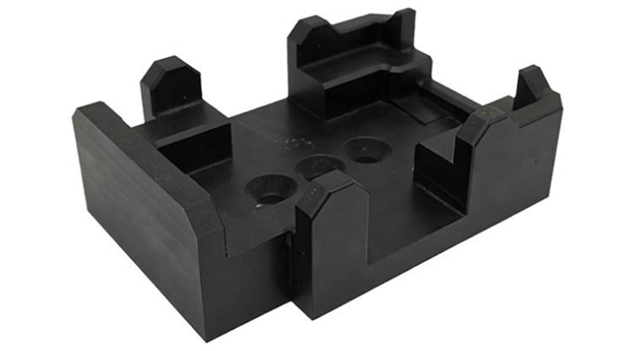
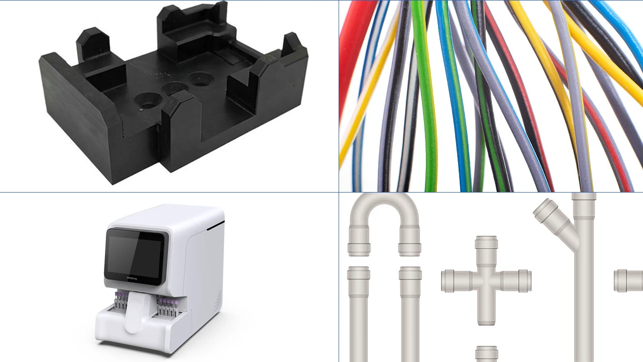
Pump housings, valve bodies, pipe fittings, flowmeter internals… These parts must simultaneously meet three key requirements: corrosion resistance, pressure resistance, and complex geometries. ETFE is currently one of the very few materials capable of meeting stringent chemical resistance requirements while enabling the production of complex shapes via injection molding. If a part’s design includes embedded channels, irregular sealing surfaces, or precision-fit interfaces, ETFE injection molding is virtually the only practical manufacturing method.
Scenario 2: Insulation Systems for Wires, Cables, and Connectors
Aviation cables, secondary instrumentation cables for nuclear power plants, 5G RF coaxial cables… These cables require insulation materials with a low dielectric constant, radiation resistance, a wide temperature range, and the ability to achieve thin-walled, uniform coating during injection molding or extrusion. ETFE is one of the standard material choices for leading global cable manufacturers in this field.
Scenario 3: Auxiliary Tools for Semiconductor and Precision Electronics Manufacturing
Wafer carriers, chemical dispensing nozzles, wet etching fixtures… Semiconductor manufacturing equipment operating in ultra-pure chemical environments requires component materials that exhibit zero contamination and zero leaching when exposed to highly corrosive media such as HF, H₂SO₄, and H₂O₂. ETFE’s high purity and chemical inertness make it the material of choice for these high-value applications.
Scenario 4: Medical Devices and Laboratory Consumables
ETFE is FDA-certified and possesses excellent biocompatibility, making it suitable for medical fluid tubing, fluidic systems in in vitro diagnostic devices, and automated liquid dispensing components in laboratories. Its resistance to sterilization (capable of withstanding steam sterilization and γ-ray irradiation) further enhances its competitiveness in the medical field.
Scenario 5: New Energy and Solar Equipment Components
Sealing gaskets for photovoltaic module frames, cable protection kits for solar tracking systems, and internal insulation components for energy storage batteries—these applications require materials to operate stably in long-term outdoor environments, where ETFE’s excellent resistance to UV and thermal aging is fully utilized.
Scenario 6: Aerospace and Military Equipment Components
ETFE’s wide temperature range (-200°C to +150°C), radiation resistance, and low volatility have earned it widespread recognition in the aerospace sector. Injection-molded ETFE parts are used in aircraft hydraulic systems, fuel system valves, and electrical insulation structural components in military radio equipment.
When Should ETFE Not Be Used for Injection Molding?
Knowing when not to use ETFE is just as important as knowing when to use it. Through Dimud’s engineering consulting services, we have helped clients avoid significant cost overruns resulting from improper material selection.
Scenario 1: Operating temperatures consistently exceed 150°C
The maximum continuous operating temperature for ETFE is 150°C. If the operating environment consistently exceeds this temperature, PFA (which can be used up to approximately 250°C) or FEP (approximately 200°C) should be considered instead of ETFE. Many industrial components operating in engine compartments or near high-temperature furnaces fall into this category.
Scenario 2: Extreme Requirements for Coefficient of Friction
If the application requires a material with an extremely low coefficient of friction (e.g., sliding bearings, piston seals), PTFE (coefficient of friction approximately 0.05) performs far better than ETFE (approximately 0.4). In such cases, unfilled or MoS₂-filled PTFE is the more suitable choice.
Scenario 3: Large-Volume, Simple-Shaped, and Cost-Sensitive Parts
If parts have simple shapes (such as flat plates, pipes, or gaskets) and can be manufactured via compression sintering or machining, PTFE is typically more cost-effective than ETFE injection molding—although the raw material prices of the two materials are similar, there is a significant difference in processing costs.
Scenario 4: Structural components requiring extremely high stiffness and hardness
ETFE’s flexural modulus (800–1100 MPa) and hardness (Shore D 60–65) are moderate by engineering plastic standards. For load-bearing components requiring extremely high structural stiffness, PEEK, PPS, or glass-fiber-reinforced nylon may be more suitable.
Scenario 5: Optically Transparent Parts Sensitive to Scratches
Although ETFE offers excellent transparency, its relatively low surface hardness makes it prone to scratching. If the application demands extremely high optical surface quality and mechanical contact is unavoidable, PMMA or PC may be superior choices in terms of cost and hardness (though, of course, the chemical resistance of these two materials is far inferior to that of ETFE).
Scenario 6: High-volume consumer products with extremely limited budgets
The raw material cost of ETFE is dozens of times higher than that of PP or ABS. When the functional requirements of a part can be met by general-purpose engineering plastics, choosing ETFE makes no economic sense. The core principle of material selection is always to use the most suitable material, not the most expensive one.
Applications of ETFE Material in Major Industries
Chemical and Fluid Handling Industry
This is the most important traditional application area for ETFE plastic injection molding. Typical components include:
- Pump bodies and covers: Lined or fully ETFE injection-molded, used in pumps for transporting strong acids and strong alkalis
- Valve balls and seats: Precision injection molding ensures excellent sealing surface accuracy
- Pipe fittings and connectors: Connecting components for corrosion-resistant piping systems
- Filter housings: Filtration systems for ultrapure chemicals
- Nozzles and dispensing heads: Precision flow control components
ETFE has become the standard material of choice in this field because it is currently one of the few injection molding materials known to simultaneously offer resistance to both HF (hydrofluoric acid) and strong oxidizing acids—a core value that other engineering plastics struggle to match.
Electrical and Electronics Industry
- High-Performance Cable Insulation: Instrumentation cables for aviation, military, and nuclear power plants
- Coaxial Connector Insulation: High-frequency, microwave, and RF systems
- Printed Circuit Board (PCB) Substrates: ETFE laminates used in high-frequency communication equipment
- Connector Housings: Industrial connectors operating in high-temperature and harsh chemical environments
- Motor Insulation Components: Internal insulation structural components for electric motors operating in high-temperature environments
Semiconductor and Microelectronics Manufacturing
- Wafer carriers and cassettes: Wafer transport containers for wet processes
- Chemical mechanical polishing (CMP) equipment components: Wear- and corrosion-resistant parts in contact with ultra-pure slurries
- Silicon wafer cleaning tank linings: Critical materials for HF etching processes
- High-purity liquid piping: Ultra-pure water and chemical delivery systems that prevent metal ion contamination
In projects serving European semiconductor equipment customers, ETFE injection-molded parts are often the core material of choice for these high-value-added projects. Please visit our Precision Injection Molding Services page for details on our full capabilities matrix for the semiconductor industry.
Medical and Life Sciences Industries
- In vitro diagnostic instrument fluidic systems: Microfluidic components in blood analyzers and gene sequencers
- Fluidic Components for Surgical Equipment: Sterilization-resistant precision fluid control components
- Laboratory Automation Equipment: Liquid-contacting parts for liquid dispensing workstations and sample processing equipment
- Imaging Equipment Components: Structural components in MRI equipment that are free of paramagnetic metals (for specific requirements)
ETFE is certified for food contact in accordance with FDA 21 CFR and meets USP Class VI biocompatibility requirements, fulfilling the basic compliance prerequisites for medical device applications.
New Energy and Photovoltaic Industries
Photovoltaic module encapsulation films: ETFE front sheet films for flexible solar panels
Cable sheaths: Insulation and sheathing for DC cables in outdoor photovoltaic power plants
Energy storage battery insulation components: Electrical insulation separators and seals within power battery packs
Hydrogen fuel cell assemblies: Seals and flow plates in proton exchange membrane fuel cells
Aerospace and Defense Industries
- Aviation Hydraulic System Fittings: Hydraulic fittings and liners operating under extreme temperatures and high pressure
- Fuel System Seals: Corrosion-resistant sealing structural components in contact with jet fuel
- Radar Radomes: Radar signal transmission windows manufactured using ETFE’s low dielectric constant
- Military Communication Cables: Signal cables operating in extreme temperature and radiation environments
Automotive and New Energy Vehicle (NEV) Industries
With the rapid adoption of new energy vehicles (NEVs), the application of ETFE plastic in the automotive industry is expanding rapidly:
Conventional Automotive Sector:
- Fuel System Components: Fuel pump bushings, fuel filter housings, and fuel injector insulation components—which must withstand long-term exposure to gasoline, ethanol-blended fuels, and various fuel additives
- Brake fluid line systems: DOT 4/5 brake fluid is corrosive to most polymers; ETFE’s resistance makes it an ideal material for high-performance brake line systems
- Engine-area wiring harnesses: Cable insulation in high-temperature areas of the engine compartment, which must withstand intermittent high temperatures and oil contamination
Applications Specific to New Energy Vehicles (NEVs):
- Internal insulation structural components for battery packs: In high-voltage (400V–800V) systems, the high-temperature resistance and electrolyte resistance of electrical insulation materials are critical
- Thermal management system tubing: Circulation tubing and fittings for battery coolant (typically containing ethylene glycol)
Internal insulation components for charging guns: Internal components of high-voltage charging interfaces that withstand mechanical stress from frequent plugging and unplugging, as well as wide ambient temperature fluctuations - Vehicle Sensor Protective Components: Sensor housings and seals designed for long-term operation in harsh environments such as rain, snow, and salt fog
Dimud provides ETFE injection molding services to automotive suppliers in Europe and North America, offering comprehensive APQP process support within the IATF 16949 quality management system framework. From DFMEA to mass production PPAP documentation, we tailor our services to meet customer requirements.
Environmental Protection and Water Treatment Industries
The demand for corrosion-resistant materials is extremely high in the water treatment and environmental engineering sectors. Thanks to its comprehensive chemical resistance, ETFE is widely used in the following applications:
- Wastewater treatment aeration equipment: Aeration heads and diffuser tube assemblies exposed to high-concentration organic acids and activated sludge environments
- Flue gas desulfurization (FGD) and denitrification equipment: Nozzles and piping components in FGD systems exposed to condensate from acidic gases such as SO₂ and HCl
- Heavy Metal Wastewater Treatment: Equipment components in electroplating wastewater and etching waste liquid treatment systems that come into contact with high-concentration heavy metal salt solutions and strong acids
- Seawater Desalination Equipment: Precision components in reverse osmosis systems that come into contact with high-salinity seawater and cleaning chemicals
- Landfill Leachate Treatment: Landfill leachate contains high concentrations of ammonia nitrogen, heavy metals, and organic pollutants, which are extremely corrosive to materials; ETFE is one of the reliable solutions
The Sustainability and Recyclability of ETFE
Given that customers in Europe and North America are increasingly focusing on carbon footprints and the circular economy, the sustainable properties of ETFE plastic warrant a separate discussion:
- 100% Thermoplastic and Recyclable: ETFE is a true thermoplastic material that can be melted down and pelletized in specialized facilities. Recycled material experiences only limited performance loss and can be used in equivalent products or downgraded applications. This represents a fundamental difference from thermosetting fluoropolymer coatings.
- Long service life reduces replacement frequency: With a service life of over 50 years, ETFE structures require virtually no replacement throughout a building’s lifecycle, thereby reducing material consumption and waste generation.
- Lightweight Design Reduces Transportation Carbon Emissions: The extremely light weight of ETFE film (approximately 1 kg/m²) results in carbon emissions during transportation that are far lower than those of glass alternatives.
- Reduced Use of Steel Structures: A 30–50% reduction in supporting structures corresponds to significant savings in steel—one of the largest sources of carbon emissions in the construction industry.
How to Collaborate with Injection Molding Suppliers to Develop ETFE Parts
The success of an ETFE injection molding project depends heavily on the depth of technical collaboration between the customer and the supplier. Below is the collaboration process recommended by the Dimud engineering team:
Step 1: Define Performance Requirements and Operating Environment
During the design phase, the following must be clearly defined:
- The types and concentrations of chemical media with which the material will come into contact;
- Operating temperature range (ambient temperature, peak high temperature, and minimum low temperature);
- Pressure and mechanical loads to be withstood;
- Electrical insulation requirements (if any);
- Dimensional tolerance requirements;
- Certification requirements (FDA, UL, medical devices, etc.).
This information directly determines the selection of ETFE grades (e.g., whether glass-fiber reinforcement is required or food-grade certification is needed) as well as subsequent mold design strategies.
Step 2: DFM Analysis (Design for Manufacturability)
ETFE’s high shrinkage rate, relatively high coefficient of thermal expansion, and difficulty in bonding require a professional DFM assessment during the design phase:
- Wall thickness uniformity: Avoid warping and sink marks caused by significant variations in wall thickness;
- Draft angle: Recommended ≥ 1.5° (ETFE’s low surface energy typically makes demolding easier than with general-purpose plastics, but steep side walls still require sufficient draft angles);
- Insert Design: If metal inserts are included, the difference in thermal expansion coefficients between ETFE and metal must be fully considered;
- Dimensional Tolerances: ETFE’s high shrinkage rate means that extremely tight dimensional tolerances require additional allowances for trial molding and mold modification.
Dimud’s DFM analysis services cover all engineering plastics and specialty fluoropolymers, helping customers identify potential risks before mold production begins and avoid rework losses caused by design flaws.
Step 3: Mold Design and Manufacturing
Based on the conclusions of the DFM analysis, mold design requires specialized optimization tailored to the characteristics of ETFE:
- Steel Selection: Prioritize stainless steel or high-corrosion-resistant, high-hardness steel;
- Cooling System: Given ETFE’s high processing temperatures, design efficient and uniform cooling channels to ensure temperature differences between areas are < 5°C;
- Ventilation System: Design adequate vent channels to prevent bubbles and defects;
- Gate System: Select appropriate gate locations and dimensions to ensure uniform melt filling of the mold.
Step 4: Trial Molding and Process Optimization
ETFE has a narrow processing window; initial trial molding typically requires comprehensive process parameter documentation and systematic optimization. Recommendations:
- Gradually increase the temperature to determine the actual processing temperature range of the material on the current equipment;
- Conduct short shot tests to confirm the filling sequence and identify areas with potential insufficient venting;
- Systematically adjust holding pressure parameters to optimize dimensional accuracy and surface quality;
- Conduct batch consistency verification to confirm process stability.
Step 5: Quality Inspection and Certification Support
Dimud provides customers with a complete chain of quality documentation:
- Material COA (Certificate of Analysis for raw material batches);
- First Article Inspection Report (FAIR);
- Process Control Documents (FMEA, Control Plan);
- Dimensional Inspection Report (CMM Coordinate Measuring Machine);
- If required, we can assist in arranging third-party chemical compatibility testing.
If you are evaluating an ETFE injection-molded part project, please visit the Dimud Precision Injection Molding Services page for more information, or contact our engineering team directly for a free project evaluation and DFM-Analyse.
Häufig gestellte Fragen
ETFE belongs to the fluoropolymer family; it is related to Teflon but is not exactly the same. “Teflon” is a registered trademark of DuPont. Originally, it referred specifically to PTFE (polytetrafluoroethylene), but the brand name has since been applied to several of the company’s fluoropolymer product lines, including FEP, PFA, and ETFE (DuPont’s ETFE products are marketed under the brand name Tefzel®). Therefore, ETFE is a “Teflon-like” fluoropolymer that, like PTFE, belongs to the fluoropolymer family and possesses excellent chemical resistance and stability across a wide temperature range. However, there are significant differences between the two in terms of molecular structure, processing methods (ETFE can be injection molded, while PTFE cannot), and mechanical properties.
ETFE is widely used in the following fields:
- Semiconductor manufacturing: High-purity, corrosion-resistant components for wet-process equipment
- Medical devices: Fluid path systems for in vitro diagnostic instruments; sterilization-resistant tubing and fittings
- Aerospace: Seals for hydraulic and fuel systems; radar antenna radomes
Under typical outdoor conditions, ETFE has an expected service life of 30 to 50 years or more. **As verified by extensive laboratory accelerated aging tests and actual engineering projects (some of which have been in operation for over 30 years), ETFE does not exhibit significant deterioration in mechanical strength, yellowing, or embrittlement during this period. For injection-molded industrial components (such as chemical pump housings and electrical insulation parts), the service life can also reach several decades when used in chemical and temperature environments appropriate for their design. After reaching the end of its service life, ETFE can be 100% recycled and reprocessed, further extending the material’s value.In terms of raw materials, the cost per square meter of ETFE film is typically higher than that of ordinary glass; however, when considering the total cost of ownership (TCO) over the entire life cycle, ETFE systems often offer a cost advantage over equivalent glass solutions. **The reasons are as follows: ETFE’s extremely light weight (approximately 1% that of glass) reduces the amount of supporting steel required by 30–50%, resulting in significant savings in structural costs; the installation process is simpler, leading to lower labor costs; ETFE’s self-cleaning properties require virtually no routine maintenance; and its service life of over 50 years means replacement is needed very infrequently. For large-scale building roofing and facade systems, taking all these factors into account, ETFE is generally a more economical and practical engineering choice than glass.
In terms of raw materials, the cost per square meter of ETFE film is typically higher than that of ordinary glass; however, when considering the total cost of ownership (TCO) over the entire life cycle, ETFE systems often offer a cost advantage over equivalent glass solutions. **The reasons are as follows: ETFE’s extremely light weight (approximately 1% that of glass) reduces the amount of supporting steel required by 30–50%, resulting in significant savings in structural costs; the installation process is simpler, leading to lower labor costs; ETFE’s self-cleaning properties require virtually no routine maintenance; and its service life of over 50 years means replacement is needed very infrequently. For large-scale building roofing and facade systems, taking all these factors into account, ETFE is generally a more economical and practical engineering choice than glass.
Yes, ETFE has excellent water resistance. **ETFE’s extremely low surface energy and high density make it virtually impermeable to water molecules, offering water resistance comparable to or even superior to that of glass. In architectural air cushion systems, ETFE film can continuously withstand rain and snow loads without leaking throughout its design life. In industrial applications, ETFE-made pipes, containers, and pump housings can be used to hold and transport various liquids—including corrosive ones—without the need for additional waterproofing treatments. Additionally, ETFE’s self-cleaning surface causes water droplets to form a large contact angle (strong hydrophobicity), which is the physical basis for why architectural ETFE films do not require special cleaning or maintenance.
Situations where ETFE is a better choice: when injection molding complex-shaped parts is required; when transparency or high light transmittance is needed; when high tensile strength and impact toughness are required; when radiation resistance is needed; and when the operating temperature does not exceed 150°C.
Situations where PTFE is a better choice: when an extremely low coefficient of friction is required (bearings, sealing surfaces, non-stick coatings); when the operating temperature consistently exceeds 150°C (PTFE can withstand up to 260°C); when parts have simple geometries that can be processed via sintering; and when there are extremely stringent requirements for chemical inertness (e.g., contact with extreme media such as fuming nitric acid).
In practical engineering applications, these two materials often serve distinct functions within the same system—for example, in chemical pumps, an ETFE injection-molded pump body provides structural support, while a PTFE shaft seal ring utilizes its extremely low coefficient of friction to ensure a reliable seal.
Zusammenfassung
ETFE plastic is one of the most valuable members of the fluoropolymer family—it bridges the technical gap between “fully fluorinated PTFE, which cannot be injection molded, and general-purpose engineering plastics, which are unsuitable for corrosive environments and wide temperature ranges.”
Chemically speaking, ETFE is produced through the copolymerization of ethylene and tetrafluoroethylene. While retaining the chemical inertness of its fluorinated segments, it achieves true injection-molding flowability, higher mechanical strength, and unique optical transparency. This gives it an irreplaceable position in high-value application areas such as chemical equipment, electrical insulation, semiconductor manufacturing, new energy, and architectural ETFE structures.
The choice between ETFE and PTFE is not an either/or decision, but rather an engineering judgment based on the specific requirements of the application, balancing processing methods, temperature ranges, mechanical properties, and friction characteristics to achieve the optimal solution.
For engineers and procurement decision-makers, the introduction of ETFE injection molding implies:
- Accepting higher material and processing costs in exchange for performance boundaries that general-purpose engineering plastics cannot achieve;
- Selecting specialized suppliers with experience in fluoropolymer processing, appropriate equipment, and quality management systems, rather than entrusting the work to ordinary general-purpose plastic injection molding factories;
- Incorporating DFM analysis early in the design phase to integrate ETFE’s shrinkage characteristics, thermal expansion differences, and mold design requirements into the product development process.
Dimud is a one-stop manufacturing partner specializing in precision injection molding and mold manufacturing, offering end-to-end services ranging from DFM analysis, precision mold design and manufacturing, injection molding, and secondary processing to supply chain management. For injection molding projects involving high-performance engineering plastics such as ETFE, our engineering team provides comprehensive professional support—from material selection recommendations to the delivery of the first part.