
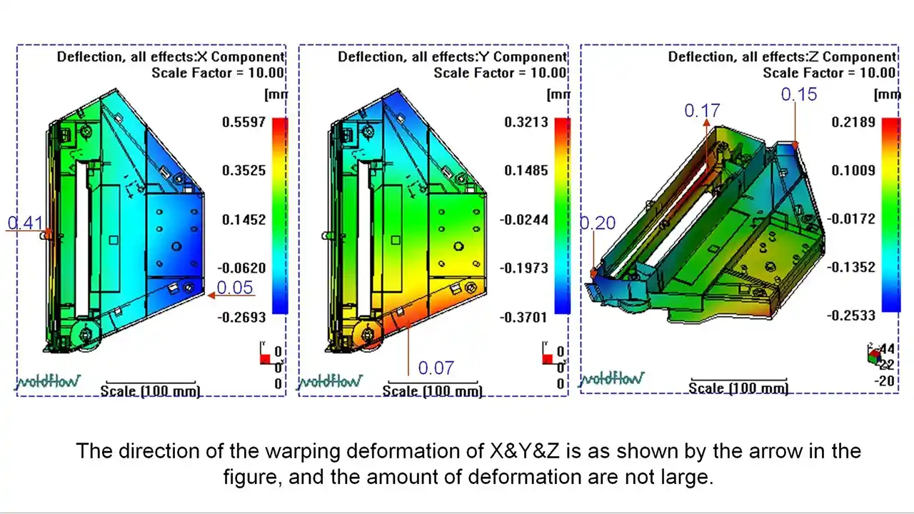
In injection molding projects, many issues don’t surface until trial runs or even mass production, leading to increased costs and extended lead times. Mold Flow Analysis can predict risks such as filling, shrinkage, voids, and warpage before the mold is manufactured, helping to optimize design and processes. What kinds of problems can it actually identify? Are the results reliable? When is it worth conducting? This article will give you a quick overview of the practical benefits and value of mold flow analysis.
Mold flow analysis (also called moldflow simulation or injection molding simulation) is a computer-based process that predicts how molten plastic will behave inside a mold cavity before any steel is cut. Using specialized software, engineers simulate the full injection cycle — from plastic fill and gate dynamics to cooling patterns and post-ejection warpage. The goal: identify defect risks early, validate gate location and mold design decisions, and reduce the costly trial-and-error that eats up tooling budgets and project timelines.
Think of it as a stress test for your mold design — done virtually, before a single machining center is touched. It won’t guarantee a perfect first shot. But it dramatically shifts the odds in your favor. Let’s get into exactly what it does, when it matters, and why skipping it is often the most expensive decision a project team makes.
What Is the Purpose of Mold Flow Analysis?
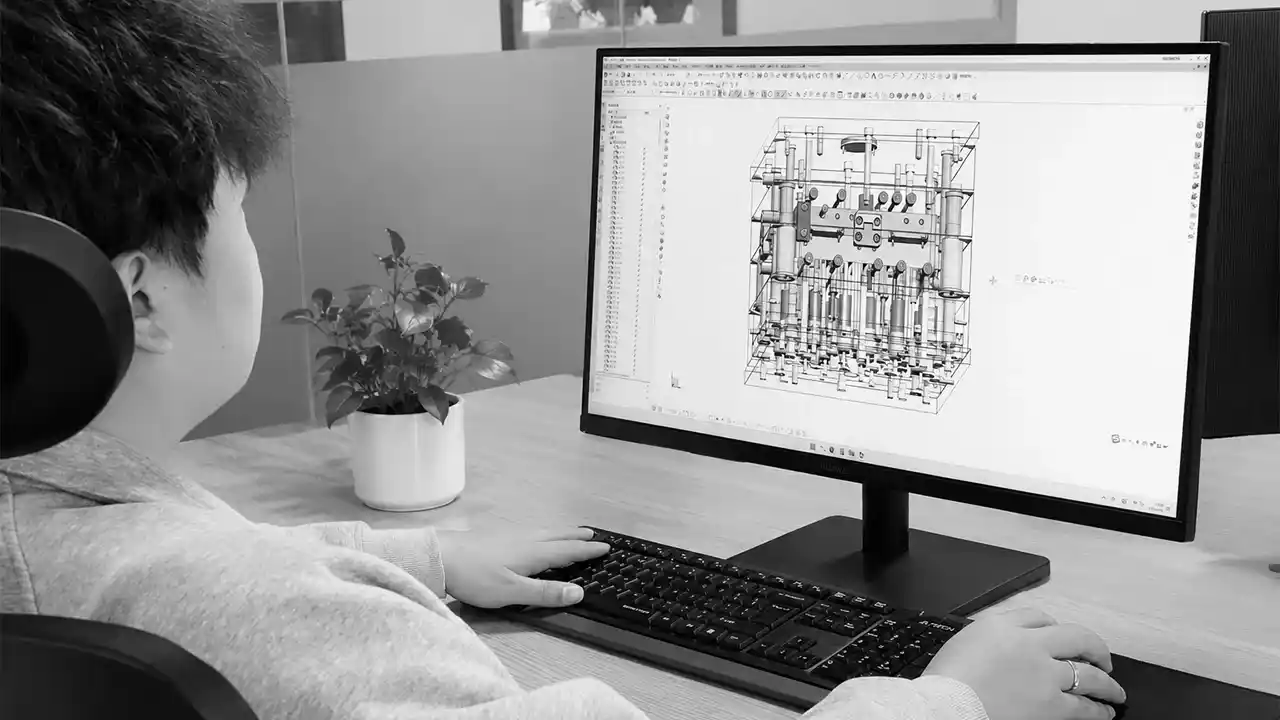
A lot of teams treat simulation as optional — something you run on big-budget, high-complexity projects, but skip on “simple” ones. That instinct has burned more projects than I can count. So what is it actually trying to solve?
The core purpose of mold flow analysis is to prevent injection molding defects before tooling begins. It identifies where problems like warpage, weld lines, air traps, sink marks, and incomplete fill will occur — and explains why. Beyond defect detection, it’s used to optimize gate location, runner design, wall thickness distribution, cooling channel layout, and injection process parameters. The outcome: fewer mold modifications, faster production ramp-up, and more consistent part quality across every production run.
Here’s something I’ve seen more than once in our engineering reviews. A client arrives with a clean model, confident the geometry is production-ready. We run a flow simulation, and within a day, we catch a weld line forming directly on a structural snap-fit feature. Not near it — on it. Had that mold been cut and trialed, the part would’ve failed during assembly. Not might have. Would have.
That’s what simulation is really for. Not optimization as a luxury — prevention as a necessity.
Catching Defects Before They Cost You
The most direct purpose is defect prediction. Simulation traces the path molten plastic takes through the cavity and flags the zones where problems form:
- Weld lines — where two flow fronts meet and fuse weakly, reducing structural strength by 20–50% depending on the resin
- Air traps — zones where displaced air can’t escape, causing burn marks, voids, or surface blistering
- Uneven cooling — which creates internal residual stress, leading to warpage after ejection
- Abrupt wall thickness transitions — which create sink marks on the surface
None of these are rare. They show up in first trials constantly, especially on parts that look simple but have hidden flow complexity.
Gate Location: The Decision That Changes Everything
Where you place the gate — the entry point for plastic — has massive downstream consequences. Shift it 5mm and you change the flow front balance, create new weld lines, or push air into a critical zone. Mold flow simulation lets you test multiple gate positions in hours. That’s a freedom you lose entirely once steel is cut.
Process Optimization Before Anyone Touches a Machine
Simulation also covers process parameters: injection speed, melt temperature, holding pressure, cooling time. Running fifty virtual combinations costs almost nothing. Running the same experiments on a real injection machine costs time, material, and machine hours — at every iteration.
How to Do Mold Flow Analysis?
The process isn’t mysterious, but there’s a real gap between running a simulation and actually interpreting one correctly. Here’s how it works in practice.
Mold flow analysis follows five steps: (1) Prepare a clean, watertight 3D CAD model of the part and mold cavity; (2) Select the specific plastic material from a validated resin database, including grade-level properties like viscosity, shrinkage, and thermal conductivity; (3) Define process parameters — injection speed, melt and mold temperature, gate type and location, cooling channel layout; (4) Run the simulation and generate visual output of fill patterns, pressure distribution, temperature maps, and defect predictions; (5) Interpret results and feed design changes back before tooling begins. Common software includes Autodesk Moldflow and Moldex3D.
Step one matters more than most people expect. A messy or geometrically incomplete CAD model produces inaccurate results. Before simulation runs, the geometry needs to be clean and properly meshed — converted into thousands of small elements that the solver can process. Poor mesh quality is one of the most consistent reasons simulation outputs don’t match real-world molding behavior.
Material Selection Is Not a Formality
The software doesn’t simulate “plastic” in general. You specify the exact resin — ABS, PC, glass-filled PA66, PEEK, whatever you’re actually using. The flow behavior of glass-filled nylon is nothing like unfilled polypropylene. Viscosity curves, shrinkage rates, thermal conductivity, crystallization behavior — all of these are loaded from the material database and directly shape your simulation results.
Use the wrong grade, or substitute a generic entry for a specialty material, and your simulation becomes decorative rather than diagnostic.
What the Output Actually Shows You
After the simulation runs, you get a set of interactive visual maps:
- Fill time animation — how the flow front progresses through the cavity in real time
- Pressure distribution — zones under high injection pressure, which correlates with weld line risk
- Temperature maps — areas that cool too slowly or unevenly, a primary driver of warpage
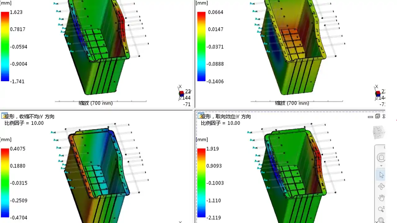
- Warpage prediction — how much the part deflects after cooling, and in which axes
- Weld line and air trap indicators — exact locations, so you can judge severity relative to the part’s function
The skill isn’t operating the software. It’s knowing which results require action, which trade-offs are acceptable, and what “good enough” actually means for your specific application. That judgment doesn’t come from software. It comes from experience.
Who Needs to Be in the Room?
Ideally, the mold engineer and product designer review results together. Simulation output often requires geometry changes, and those changes need sign-off from whoever owns the design. When simulation teams and design teams are siloed, changes happen in isolation — or worse, don’t happen at all.
What Does Mold Flow Analysis Actually Detect?

People generally know simulation “finds problems.” But which problems? The specifics are more actionable than the vague summary.
Mold flow analysis detects: warpage and dimensional distortion from uneven cooling or residual stress; weld lines where flow fronts meet at low temperature and bond poorly; air traps that produce burn marks or subsurface voids; short shots from insufficient fill pressure or overly restricted flow paths; sink marks from wall thickness imbalances; jetting from gate velocity mismatches; and fill imbalance in multi-cavity molds. Each defect has a distinct root cause, and simulation identifies both the symptom and the source — giving engineers something to act on, not just a problem to name.
Let me be specific about the ones that surprise clients most.
Warpage: The Silent Failure Mode for Precision Parts
Warpage is probably the most feared defect in precision injection molding — and the hardest to fix after the fact. A part looks dimensionally correct inside the mold. Once ejected and cooled to room temperature, it bows, twists, or cups. Sometimes fractions of a millimeter. Sometimes several.
The root causes are almost always tied to cooling asymmetry (one side cools faster than the other, generating internal stress) or fiber orientation in glass-filled materials. Simulation predicts warpage deflection across all three axes — letting engineers redesign the cooling circuit or adjust wall geometry before any steel is machined.
For precision mold manufacturing projects with tight assembly tolerances, catching warpage in simulation isn’t optional. It’s the only practical way to manage it.
Weld Lines: A Structural Issue That’s Easy to Miss Visually
Weld lines form where two flow fronts converge and fuse. The bond at that junction is always weaker than the surrounding base material — sometimes significantly. In a cosmetic housing, a well-placed weld line might be acceptable. On a snap-fit cantilever or a pressure-bearing wall, it’s a failure mode waiting to be triggered.
Simulation shows exactly where weld lines will form. Engineers can then reposition gates, adjust injection speed, or design overflow wells to push weld lines into non-critical zones.
Multi-Cavity Fill Balance
Multi-cavity molds — where multiple identical parts are produced per cycle — require every cavity to fill at the same rate. Imbalance means some cavities overfill (flash, dimensional error) while others underfill (short shot, incomplete geometry). Mold flow simulation identifies runner geometry that achieves natural balance, which matters enormously for consistent quality at production volume.
Mold Flow Analysis in Injection Molding: When Does It Actually Make Sense?
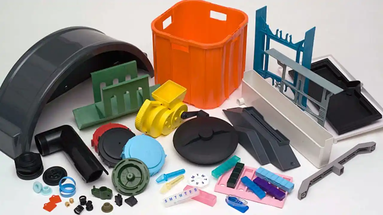
Simulation isn’t free. It takes engineering time. So when does it genuinely pay off, and when can experience substitute?
In injection molding, mold flow analysis makes the strongest case for: complex geometries and long flow paths; thin-walled parts where fill pressure is marginal; engineering resins with unpredictable shrinkage behavior; precision components where dimensional accuracy directly affects assembly or function; multi-cavity tools requiring fill balance; and any project where mold modification costs would be prohibitive. For simple, symmetrical parts in commodity resins with short, unobstructed flow paths, experienced engineers can often rely on intuition — though even there, simulation catches gate placement errors that experience still misses occasionally.
Here’s how I think about it practically.
The cost of a mold flow analysis is typically a small fraction of total tooling investment. For a mold in the $15,000–$50,000 range, simulation might add $500–$2,000 in pre-production time. A single mold modification — gate relocation, cooling channel rework, runner redesign — can cost $1,000–$10,000 and add two to four weeks of delay. The math is almost always in simulation’s favor.
When It’s Non-Negotiable
Some project types make skipping simulation genuinely indefensible:
Automotive structural and visible components — tolerances of ±0.1mm or tighter, often in glass-filled materials with complex warpage behavior. One mold revision here can cost more than the original simulation budget by an order of magnitude.
Medical device enclosures and functional components — where dimensional accuracy affects regulatory compliance, assembly clearances, and device reliability. These molds don’t get informal field fixes.
Consumer electronics housings with Class A surfaces — where weld lines and sink marks are cosmetically unacceptable. Customers return products for this. Brands remember.
Large parts with long flow paths — where the plastic has to travel significant distance, pressure drop accumulates, and short shots become a real risk.
When Experience Can Substitute
A simple, symmetrical cap with uniform wall thickness in polypropylene? A senior mold engineer with 20 years of hands-on experience probably doesn’t need software to confirm gate placement. The geometry is forgiving, the material is well-understood, and the failure modes are predictable.
The danger is applying that same confidence to parts that look simple but have hidden complexity — internal ribs, asymmetric cooling requirements, load-bearing zones in unexpected locations. That’s where intuition-only calls get expensive.
How Accurate Is Mold Flow Simulation, Really?

If simulation is so useful, why do parts still come out wrong after running one? It’s a fair challenge — and the honest answer reveals something important about how to use these tools correctly.
Mold flow simulation accuracy depends heavily on input quality: material data precision, geometry cleanliness, and realistic process parameters. Fill analysis and pressure distribution predictions are generally reliable under good conditions. Warpage prediction is less consistent, especially for glass-filled and semi-crystalline materials where fiber orientation effects introduce compounding uncertainty. Simulation is best understood as a high-value risk reduction tool, not a guarantee of first-shot success. The experience of the engineer interpreting the results matters as much as the software generating them.
The Material Data Problem
Most simulation platforms pull from a resin database — but not every grade of every polymer is accurately represented. When your specific material isn’t in the database, you use the closest available match. For well-characterized commodity resins like ABS, PP, and PC, those matches are usually accurate enough. For specialty grades — high-fill composites, custom blends, novel engineering resins — the database entry may be years old or based on slightly different testing conditions.
This is why material knowledge matters as much as simulation capability. Engineers who understand resin behavior at a fundamental level use simulation results differently than those who treat output as definitive.
Warpage Prediction: More Directional Than Absolute
Warpage modeling involves simultaneously computing shrinkage, residual stress fields, fiber orientation (in filled materials), and post-ejection relaxation. Each introduces uncertainty. In practice, simulation usually gets the direction of warpage right and the relative magnitude right — meaning it correctly predicts which areas will deflect most, and in which direction. The absolute numbers are sometimes off by a meaningful margin.
The practical approach: use warpage simulation to guide design decisions — cooling circuit layout, wall thickness distribution, gate positioning — rather than as a dimensional prediction to report against drawing tolerances.
Why Interpretation Beats Raw Output
Two engineers can look at the same simulation and reach different conclusions. A weld line in a non-visible, non-structural area might be entirely acceptable. The same weld line on a snap-fit arm or a sealing surface is a failure mode. Knowing the difference — and knowing which trade-offs are engineering decisions versus which are risks — is what makes simulation genuinely valuable in production.
That’s engineering judgment. Software doesn’t provide it.
Can Dimud Perform Mold Flow Analysis?

Clients often ask this early in a project — not because they doubt us, but because they’ve been quoted “simulation included” by other suppliers and received a color printout with no engineering discussion behind it. Fair skepticism.
Yes, Dimud provides professional mold flow analysis as part of our pre-tooling engineering services. Our mold engineers run injection molding simulations covering fill analysis, cooling circuit evaluation, warpage prediction, weld line and air trap detection, and gate location optimization. Results are reviewed with your design team, and changes are incorporated before mold manufacturing begins. Mold flow simulation at Dimud is integrated with DFM review and mold design — not offered as a standalone checkbox.
When a client sends us a 3D model for a new project, our team doesn’t open a mold design file on day one. We start with a DFM review — examining the geometry for manufacturability risks, material suitability, draft angles, wall thickness consistency, and feature feasibility. For any part with meaningful complexity, mold flow simulation runs as part of that initial phase.
What We Simulate and What We Do With the Results
Our simulation workflow covers the cases that actually drive decisions:
Fill analysis — confirming the gate location, runner geometry, and injection parameters produce balanced, complete cavity fill without jetting or hesitation marks.
Cooling analysis — evaluating whether the cooling channel layout produces sufficiently uniform temperature distribution, or whether hot spots will drive warpage or extend cycle time unnecessarily.
Warpage prediction — assessing post-ejection dimensional deviation, particularly important for parts with assembly interfaces, tight fit requirements, or snap-fit features.
Weld line and air trap mapping — identifying location and approximate severity relative to the part’s structural requirements and cosmetic zones.
The output goes to both our mold designers and to the client. If simulation flags a design change, we discuss it — we don’t absorb it silently and hope it disappears during trialing.
Why Integration Matters More Than the Tool Itself
The part of this that matters most isn’t which software we use. It’s that our mold engineering team runs simulation, conducts DFM review, designs the mold, and oversees production — all in-house, all in conversation with each other.
The engineer who flags a warpage risk in simulation is the same engineer who designs the cooling circuit to address it. The same engineer reviews the first trial shot. That continuity is uncommon. It’s also why we consistently maintain a high first-pass mold acceptance rate across complex tooling projects.
Does Mold Flow Analysis Add to Tooling Cost — or Reduce It?

Cost is always part of the conversation. And it should be. So let’s answer this directly rather than dancing around it.
Mold flow analysis consistently reduces total tooling cost by preventing mold modifications before they happen. The simulation fee is small relative to tooling investment, while each mold modification — gate relocation, cooling channel rework, runner geometry changes — typically costs $1,000–$10,000 and adds two to four weeks of delay. On complex tooling, a single prevented modification covers the simulation cost multiple times over. For high-volume programs or tight-tolerance parts, the cost-benefit calculation is straightforward.
The tooling stage is where projects go sideways — not because engineers aren’t competent, but because the interaction between geometry, material behavior, and process creates combinations that are genuinely difficult to predict without simulation. Even experienced toolmakers will tell you: some failures only become visible in hindsight.
The Timeline Cost of Skipping It
When a mold comes back from first trial with a warpage problem that simulation would have caught, here’s what typically unfolds:
- Trial review and defect identification: 1–3 days
- Engineering root cause analysis: 1–2 days
- Mold modification (if correctable in existing steel): 3–10 days
- Re-trial and dimensional validation: 2–5 days
- Total schedule impact: 2–4 weeks minimum
If the modification isn’t feasible in the current steel and the mold requires significant rework, that window extends to 6–10 weeks, with costs that can approach the original tooling price.
Compare that to simulation running over 2–3 days before tooling begins, identifying the same risk, and driving a geometry adjustment at the 3D file stage — a change that costs almost nothing to implement.
Where the Savings Actually Accumulate
The savings from simulation aren’t always dramatic in any single line item. They add up across the project lifecycle:
- No gate relocation = no steel welding or re-EDM machining
- Balanced cooling = faster, more stable cycle times from the start
- Predicted warpage = no secondary fixturing or post-production correction
- Pre-identified weld lines = no cosmetic rework on Class A surfaces
For injection molding services running high-volume production programs, even a 5% improvement in cycle time efficiency — the kind that better cooling design produces — compounds significantly across millions of shots. That’s not a theoretical benefit. It’s a real, measurable return that clients with long production runs see in their cost-per-part figures.
Conclusion
Mold flow analysis is one of those things that feels optional until you’ve paid the price for skipping it. The best time to run it is before anyone cuts steel — when design changes are fast, cheap, and consequence-free. By the time a mold is in trial, that window is gone. If you’re moving a design toward tooling and haven’t yet run a simulation, that’s worth pausing on. Reach out to Dimud’s engineering team — we’ll walk you through what simulation would actually show for your part, and what it would take to address any risks before they become mold rework.