

Custom Die Casting Molds Built for Precision and Production Scale
From tooling design to first shot approval — we engineer molds that hold tight tolerances across high-volume runs.
- Mold Life Up to 500,000 Shots
- Tolerance Within ±0.05mm
- Mold Sampling Within 3 Days

What Is a Die Casting Mold?
A die casting mold—also referred to as a die casting die or die casting tooling—is a precision-engineered metal tool used to produce complex, high-accuracy components by injecting molten metal under high pressure into a hardened steel cavity.
Unlike sand casting or gravity casting, die casting molds are designed for repeatable, high-volume production, where every part must meet consistent dimensional and surface quality standards across thousands—or hundreds of thousands—of cycles.
The mold itself consists of two primary halves: the cover die (fixed half) and the ejector die (moving half). Together, they form a sealed cavity that defines the exact geometry, wall thickness, and surface texture of the finished part.
Types of Die Casting Processes Supported
| Process Type | Characteristics | Typical Applications |
|---|---|---|
|
Hot Chamber Die Casting |
Fast cycle times, suitable for low-melting-point alloys |
Zinc, magnesium components |
|
Cold Chamber Die Casting |
Higher injection pressure, handles high-melting alloys |
Aluminum structural parts |
|
High Pressure Die Casting (HPDC) |
Superior surface finish, tight tolerances |
Automotive, electronics housings |
|
Low Pressure Die Casting (LPDC) |
Better material density, reduced porosity |
Wheels, structural castings |
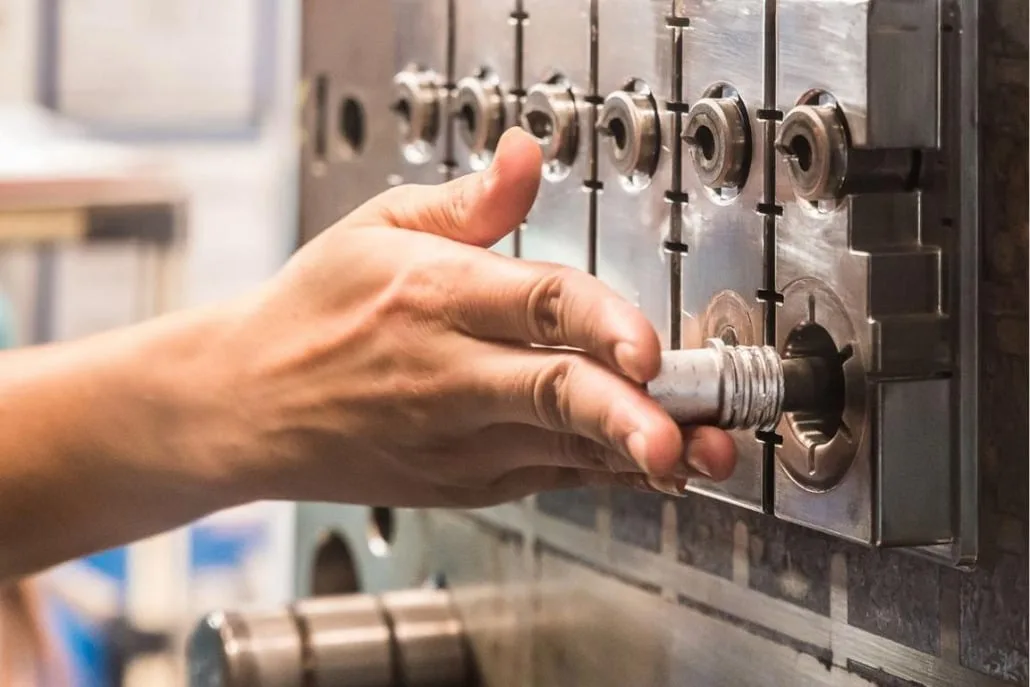
Key Components of a Die Casting Mold
- Cavity & Core — Define the internal and external geometry of the cast part
- Runner System & Gates — Control the flow path and injection speed of molten metal
- Cooling Channels — Regulate thermal distribution to minimize warpage and shrinkage
- Ejector System — Ensure clean, damage-free part release after solidification
- Overflow Wells & Venting — Prevent gas entrapment and surface porosity defects
- Slide & Lifter Mechanisms — Enable undercuts and complex geometries that cannot be straight-pulled
Critical Process Parameters in Die Casting
Understanding these parameters is essential for evaluating mold design quality and production feasibility:
- Injection Pressure — typically ranges from 10 to 175 MPa depending on alloy and part complexity
- Mold Temperature — Aluminum: 150–250°C; Zinc: 100–150°C; Magnesium: 180–280°C
- Cycle Time — Driven by wall thickness, cooling channel design, and alloy solidification rate
- Draft Angle — Minimum 0.5°–2° required on vertical walls to ensure clean ejection
- Wall Thickness — Recommended 1.5mm–5mm for aluminum; 0.5mm–3mm for zinc
- Shrinkage Rate — Aluminum: ~0.5–0.7%; Zinc: ~0.3–0.5%; must be compensated in mold design
How Die Casting Molds Differ from Other Tooling Types
| Process Type | Characteristics | Typical Applications | Table Header |
|---|---|---|---|
|
Comparison |
Die Casting Mold |
Plastic Injection Mold |
Sand Casting |
|
Material |
Metal alloys (Al, Zn, Mg) |
Thermoplastics |
Metal alloys |
|
Pressure |
High (10–175 MPa) |
Medium (35–140 MPa) |
None / gravity |
|
Surface Finish |
Excellent (Ra 0.8–3.2μm) |
Excellent |
Rough |
|
Dimensional Accuracy |
±0.1mm – ±0.3mm |
±0.05mm – ±0.2mm |
±0.5mm+ |
|
Tooling Cost |
High |
Medium–High |
Low |
|
Production Volume |
Production Volume |
Production Volume |
Production Volume |
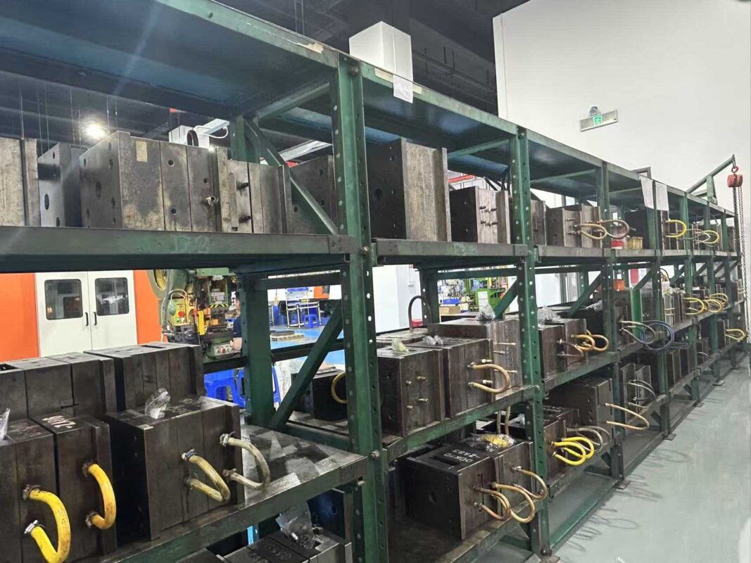
Our die-casting molds can reach unexpected heights
Engineered for complexity. Built for production. Every mold we deliver is designed to perform consistently from the first shot to the last.
| Application Parts | Key Grinding Requirements |
|---|---|
|
Capability |
Specification |
|
Mold Size Range |
Up to 2,000 mm × 1,800 mm |
|
Mold Weight Capacity |
Up to 30 tons per set |
|
Dimensional Tolerance |
±0.1mm (standard) / ±0.05mm (precision) |
|
Surface Roughness |
Ra 0.8μm – Ra 3.2μm |
|
Cavity Configuration |
Single cavity / Multi-cavity / Family mold |
|
Mold Base Standard |
DME / HASCO / Custom |
|
Tool Steel Hardness |
44–52 HRC (post heat treatment) |
|
Cooling System |
Conformal cooling / Baffle / Bubbler |
Supported alloy types
Aluminum Die Casting Mold
Optimized for A380, A383, ADC12 — the most widely used alloys in automotive and electronics applications. Mold design accounts for aluminum’s thermal expansion rate and gate erosion characteristics.
Zinc Die Casting Mold
Engineered for Zamak 3, Zamak 5, ZA-8. Supports ultra-thin wall sections down to 0.5mm with fine surface detail retention — ideal for precision hardware and connector housings.
Magnesium Die Casting Mold
Designed with reinforced venting and controlled temperature management to handle magnesium’s high reactivity and fast solidification behavior.
Copper Alloy Die Casting Mold
Available for specialized industrial applications requiring high thermal or electrical conductivity components.
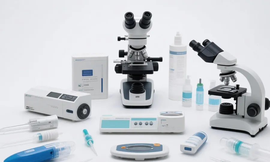
How do we ensure and verify quality?
| Inspection Stage | Method |
|---|---|
|
Steel Incoming Inspection |
Material cert verification + hardness testing |
|
Machining Dimensional Check |
CMM full-cavity mapping |
|
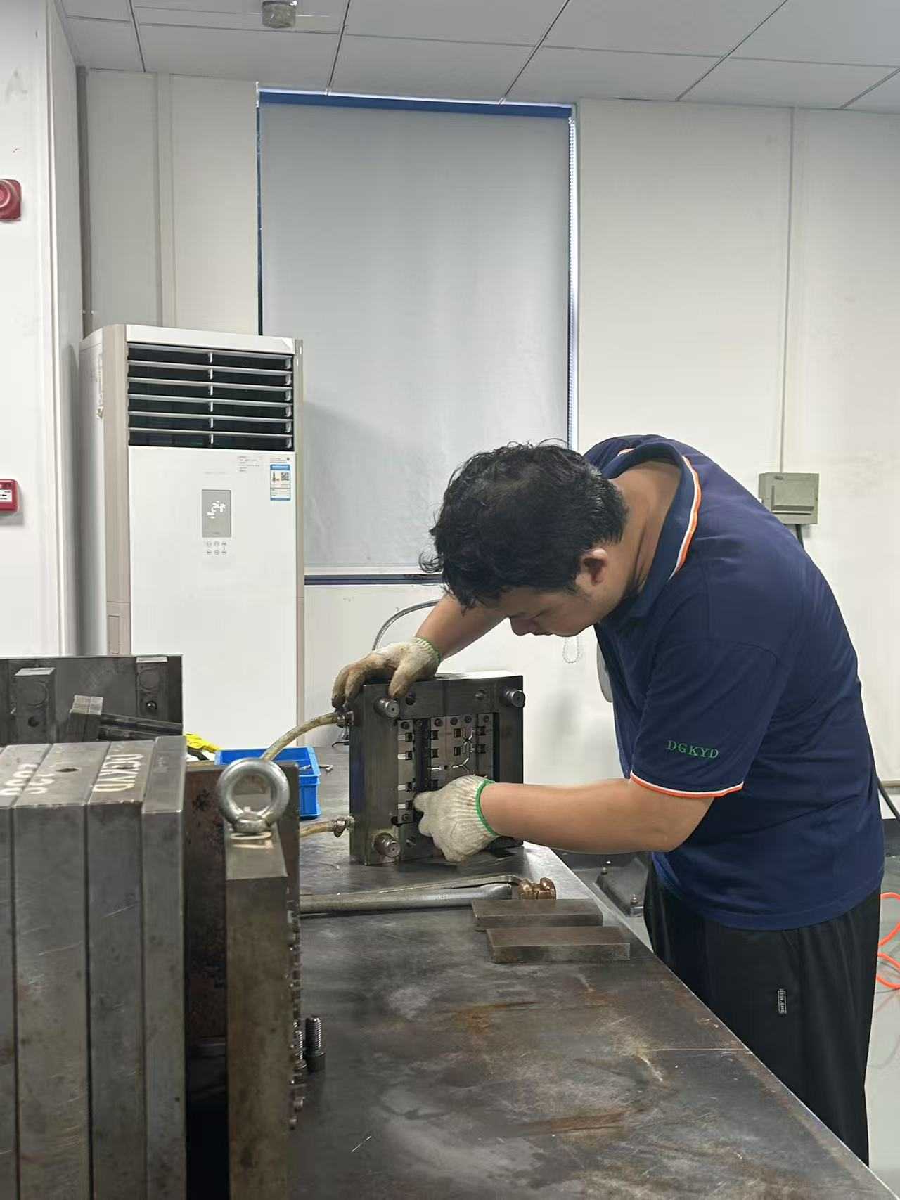
Mold Trial Evaluation |
First shot dimensional report + surface defect analysis |
|
Gate & Runner Optimization |
Fill balance verification across all cavities |
|
Thermal Performance Check |
Mold temperature distribution test per production cycle |
|
Cavity Configuration |
Single cavity / Multi-cavity / Family mold |
|
Final Tooling Sign-off |
FAI report + T1 sample approval before shipment |
Precision Manufacturing Solutions for Your Industry
Different industries have vastly different technical thresholds and compliance requirements when it comes to ensuring and verifying quality in die-casting molds. We specialize in four core industries, transforming our mold engineering capabilities into competitive advantages for our customers’ products.

Automotive components are subject to extremely stringent requirements for dimensional consistency and batch-to-batch stability; even the slightest deviation can lead to assembly failures or safety hazards. At the same time, automotive manufacturers impose mandatory requirements on suppliers regarding delivery lead times and quality traceability.
Our Solution:
To address the significant wall thickness variations and complex internal geometries of automotive structural components, we incorporate mold flow simulation during the mold design phase to optimize gate layout and cooling systems, ensuring uniform density and the absence of shrinkage defects in every casting. We provide a comprehensive FAI report and Process Capability Index (Cpk) data prior to mold shipment.
Key Applications:
- Transmission housings / Engine brackets
- EV battery trays / Motor housings
- Steering system components
- Structural aluminum die castings for vehicle bodies
Medical device components are subject to strict regulatory requirements regarding material cleanliness, dimensional repeatability, and traceability. Lubricant residues, mold cavity contamination, or dimensional variations between batches during the die-casting process can render an entire batch non-compliant, resulting in significant losses.
How we address this:
Medical die-casting molds are manufactured under fully enclosed, cleanroom-controlled conditions using medical-grade lubricants, and the cavity materials undergo rigorous cleanliness validation. We provide complete process records and traceability reports for every production batch to support our customers in meeting FDA and ISO 13485 audit requirements.
Key Applications:
- Diagnostic Device Housings
- Surgical Instrument Components and Mounting Brackets
- Precision Housings for Medical Imaging Equipment
- Frame Components for In Vitro Diagnostic (IVD) Instruments

Consumer and industrial electronics products undergo rapid iterations, requiring short mold development cycles. At the same time, components feature thin walls and high aesthetic standards; conventional die-casting processes are prone to surface defects such as cold shuts and porosity, which directly affect product appearance and heat dissipation performance.
Our Solution:
For thin-walled electronic structural components, we employ high-speed filling gate designs combined with vacuum-assisted die-casting to effectively suppress porosity and short-shot issues. The cavity surfaces undergo mirror polishing to directly meet the surface finish requirements for cosmetic parts, thereby reducing the need for post-processing steps.
Main Applications:
- Telecom Enclosures and Heat Sinks
- Industrial Controller Housings
- Connector and Terminal Brackets
- Precision Structural Components for Semiconductor Equipment

The robotics and energy storage industries are currently experiencing rapid expansion, and the timeline for moving products from prototypes to mass production is extremely tight. At the same time, components such as joint structures and battery module housings must meet dual requirements for lightweight design and structural strength—a challenge that traditional machining methods struggle to address.
Our Solution:
We offer a phased development path ranging from **prototype tooling to production tooling**, helping customers rapidly validate their products without committing to large upfront tooling investments. To address weight reduction needs, we focus on aluminum-magnesium alloy die-casting solutions, which reduce part weight while maintaining structural rigidity.
Key Applications:
- Robot Joint Housings and Gearbox Covers
- Energy Storage Module Frames
- Drone Bodies and Power System Housings
- Industrial Automation Structural Parts
Frequently Asked Questions About Die-Casting Molds
Prototype tooling: 2–3 weeks. Single-cavity production mold: 4–6 weeks. Multi-cavity or complex tooling: 6–10 weeks. Timeline starts after DFM sign-off and 2D/3D drawing approval.
No technical difference. "Die casting die" is standard terminology in North America and Europe; "die casting mold" is more commonly used in Asian manufacturing contexts. Both refer to the same hardened steel tooling.
3D: STEP, IGES, SOLIDWORKS, Parasolid, Catia.
2D: DWG, DXF, PDF with GD&T callouts.
Only have a sample or sketch? Contact us — reverse engineering is available.
Porosity comes from trapped gas during filling and shrinkage during solidification. It's controlled through gate and runner design, overflow venting placement, and mold flow simulation before steel cutting — not corrected after the fact.
Alloy selection depends on strength requirements, wall thickness, operating environment, and cost targets. We align on material before tooling design begins — changing alloy after mold completion typically requires significant rework.
Steel grade, heat treatment quality, cooling system design, injection pressure, and maintenance frequency. General benchmarks:
- Aluminum die casting mold: 100,000–300,000 shots
- Zinc die casting mold: 500,000–1,000,000+ shots
- Magnesium die casting mold: 80,000–200,000 shots
Yes. We offer soft tooling for early validation (500–5,000 shots) and hardened production tooling rated for 200,000–500,000+ shots. Customers can start with prototype tooling and scale without switching suppliers.
Yes — it's standard, not optional. We run fill pattern, air trap, shrinkage, and thermal analysis before any steel is cut. Results are shared with the customer before mold design is finalized.
We share DFM reports, mold design packages, in-process photos/videos, and CMM dimensional reports at each milestone. T1 samples ship with full inspection data before production is released. Third-party inspection (SGS, Bureau Veritas) is also supported.
| Defect | Root Cause | Tooling-Stage Solution |
|---|---|---|
| Porosity | Trapped gas / shrinkage | Optimized venting + mold flow simulation |
| Cold shut | Insufficient fill speed | Gate size and location adjustment |
| Flash | Poor parting line fit | Precision mold base machining |
| Warpage | Uneven cooling | Balanced cooling channel design |
| Sink marks | Wall thickness variation | DFM wall thickness optimization |
Ready to Start Your Die Casting Mold Project?
Get a free DFM review and quote within 24 hours.