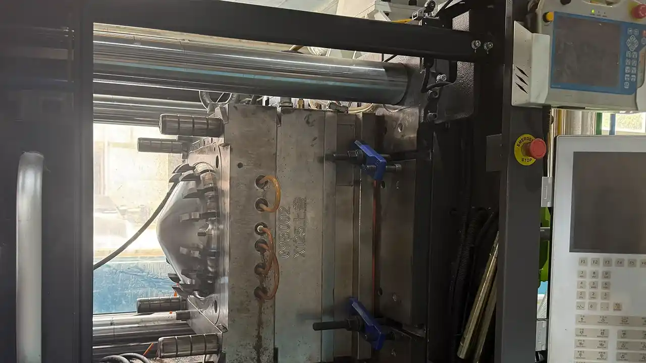

Was ist passiert? PET ist ein teilkristallines Polymer – und teilkristalline Polymere verhalten sich unterschiedlich, je nachdem, ob sie während des Formprozesses kristallisieren oder nicht. Ein Ingenieur, der bisher nur mit amorphen Polymeren wie ABS oder PC gearbeitet hat, wird das Kristallisationsverhalten von PET als ein System von Variablen erleben, mit denen er sich bisher noch nicht auseinandersetzen musste: Die Formtemperatur bestimmt, ob das Bauteil amorph-transparent oder kristallin-opak ist; unzureichende Trocknung führt zu hydrolytischem Abbau, der das Molekulargewicht dauerhaft verringert, noch bevor das Material überhaupt in den Zylinder gelangt; und der Unterschied zwischen PET in Flaschenqualität und PET in Spritzgussqualität ist keine Nebensache – er entscheidet darüber, ob der Prozess überhaupt durchführbar ist.
Dieser Leitfaden soll diese Wissenslücke schließen. Auf der Grundlage der Fertigungserfahrung von Dimud mit PET-Kunststoffprogrammen in den Bereichen Automobilsteckverbinder, Komponenten für medizinische Geräte, Elektronikgehäuse und Teile für die Robotermontage vermittelt er die materialwissenschaftlichen Grundlagen, Prozesssteuerungen, die Logik der Formkonstruktion sowie den Compliance-Rahmen, die PET-Spritzgussprogramme benötigen, um vom ersten Spritzguss bis zur Serienproduktion gleichbleibend hochwertige Ergebnisse zu liefern.
Was ist PET-Kunststoff?
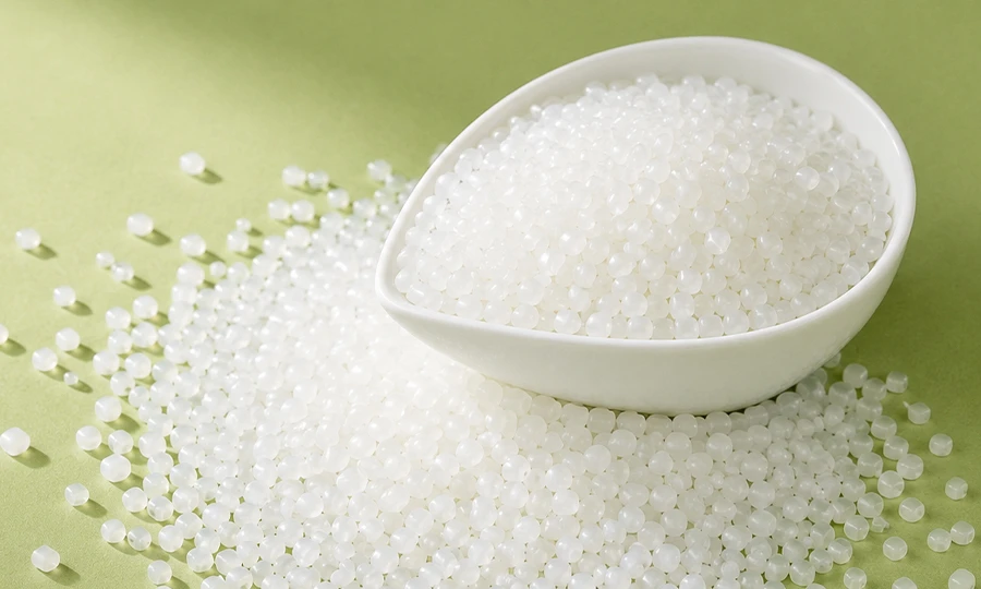
Polyethylenterephthalat – allgemein als PET-Kunststoff abgekürzt – ist ein teilkristalliner thermoplastischer Polyester, der durch Polykondensation von Ethylenglykol (EG) und Terephthalsäure (PTA) oder Dimethylterephthalat (DMT) hergestellt wird. Die so entstehende Polymerkette besteht aus abwechselnden aromatischen Ring-Einheiten und flexiblen aliphatischen Segmenten, die durch Estergruppen (-CO-O-) verbunden sind. Dadurch entsteht eine molekulare Architektur, die je nach thermischer Vorgeschichte sowohl eine amorphe als auch eine kristalline Kettenanordnung annehmen kann.
Dieses Zweiphasenverhalten – amorph oder kristallin – macht PET-Kunststoff gleichzeitig zu einem der vielseitigsten und zugleich verarbeitungsempfindlichsten technischen Thermoplaste. Zu verstehen, welcher Zustand für eine bestimmte Anwendung angestrebt wird und wie dieser durch die Gestaltung der Form und des Verarbeitungsprozesses konsistent erreicht werden kann, bildet die Grundlage jedes erfolgreichen PET-Spritzgussprogramms.
Die zwei Gesichter von PET:
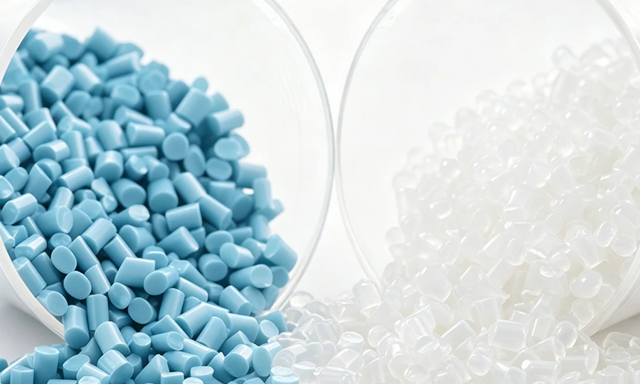
- Amorphes PET (schnell abgeschreckt, geringe Kristallinität < 5%): Optisch transparent, flexibel, geringere Dichte (~1,33 g/cm³). Dies bildet die Grundlage für PET-Flaschenvorformlinge, Lebensmittelschalen und transparente Verpackungen. Beim Spritzgießen erfordert amorphes PET niedrige Formtemperaturen (10–20 °C) und eine schnelle Abkühlung, um eine Kristallisation zu verhindern.
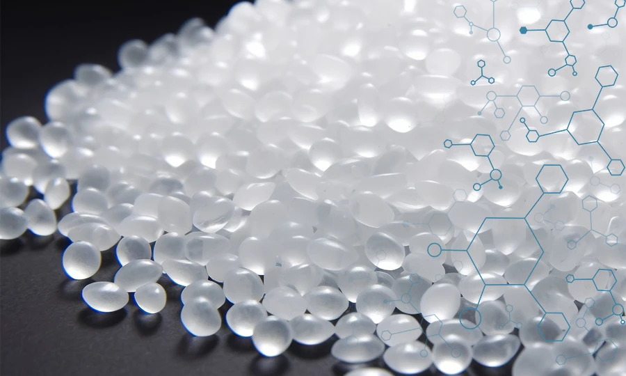
- Teilkristallines / kristallines PET (langsam abgekühlt oder geglüht, Kristallinität 20–40%): Undurchsichtiges oder durchscheinendes Weiß, steif, höhere Dichte (~1,38–1,40 g/cm³), deutlich bessere Wärmebeständigkeit (HDT bis zu 220–240 °C bei glasfaserverstärkten Typen). Dies bildet die Grundlage für Präzisionsbauteile in der Automobilindustrie, der Elektronik und der Medizintechnik – und steht im Mittelpunkt der PET-Spritzgussprogramme von Dimud.
Was PET-Kunststoff bietet, was konkurrierende Polymere nicht können:
- Dimensionsstabilität: geringe Schrumpfung (1,5–2,21 TP3T ungefüllt; 0,2–0,81 TP3T bei glasfaserverstärkten Typen) in kontrollierter teilkristalliner Form
- Chemische Beständigkeit: Hervorragende Beständigkeit gegenüber Kraftstoffen, Schmierstoffen, verdünnten Säuren und den meisten organischen Lösungsmitteln – entscheidend für Anwendungen in der Automobilindustrie und in der Industrie
- Dielektrische Eigenschaften: stabile Dielektrizitätskonstante und niedriger Verlustfaktor über einen breiten Frequenzbereich – besonders geschätzt für Anwendungen im Bereich elektronischer Steckverbinder
- Konformität mit Lebensmittel- und Medizinproduktenvorschriften: Zulassung gemäß FDA 21 CFR und EU 10/2011 für den Kontakt mit Lebensmitteln; Konformität mit USP Klasse VI und ISO 10993 bei medizinischen Qualitäten verfügbar
- Recyclingfähigkeit: PET trägt den Recycling-Code #1 und ist der weltweit am häufigsten recycelte Kunststoff – damit weist es Nachhaltigkeitsmerkmale auf, mit denen nur wenige technische Kunststoffe mithalten können
Was Ihnen PET-Kunststoff kostet:
- Obligatorische und strenge Vortrocknung (< 0,02% Feuchtigkeit) – der hydrolytische Abbau ist irreversibel und beeinträchtigt die Leistungsfähigkeit des Bauteils erheblich
- Kristallisationssteuerung: Die Formtemperatur muss präzise geregelt werden, um den angestrebten Kristallisationsgrad zu erreichen; eine ungleichmäßige Kühlung führt zu ungleichmäßigen Teileigenschaften
- Höhere Verarbeitungstemperatur als bei handelsüblichen Thermoplasten: Zylindertemperaturen von 260–290 °C, wobei eine Überhitzung zu vermeiden ist
- Längere Zykluszeiten bei Programmen für kristallines PET aufgrund des Zeitaufwands für die kontrollierte Kristallisation
Unter Dimud, PET-Kunststoffprogramme gehören zu unseren technisch anspruchsvollsten Materialkategorien – sie erfordern die Integration von Granulatsortenauswahl, Trocknungsüberprüfung, Formtemperaturregelung und Kristallinitätsmanagement in ein einziges, koordiniertes Produktionssystem. Das Ergebnis ist – bei korrekter Umsetzung – ein Material, das die meisten Alternativen in Bezug auf das Preis-Leistungs-Verhältnis für Anwendungen im Präzisionsmaschinenbau übertrifft.
PET-Sorten: Flaschen-PET, Spritzguss-PET und verstärktes PET
Die wichtigste Unterscheidung zwischen verschiedenen PET-Typen wird von Ingenieuren, die nicht aus dem Verpackungsbereich kommen, häufig übersehen: PET in Flaschenqualität und PET in Spritzgussqualität sind nicht austauschbar, und die Verwendung des falschen Typs ist die Hauptursache für einen erheblichen Teil der Fehler bei der PET-Verarbeitung.
PET in Flaschenqualität (APET / PETG für Verpackungen)
PET in Flaschenqualität ist für das Blasformen und das Thermoformen ausgelegt – Verfahren, bei denen eine hohe Schmelzfestigkeit, eine langsame Kristallisationskinetik und die Fähigkeit zur Herstellung optisch klarer, biaxial orientierter Folien und Behälter von Vorteil sind. Seine intrinsische Viskosität (IV) liegt typischerweise im Bereich von 0,72 bis 0,85 dL/g.
Warum PET in Flaschenqualität beim Spritzgießen von technischen Bauteilen versagt: Aufgrund der langsamen Kristallisationsgeschwindigkeit ist es selbst bei erhöhten Formtemperaturen schwierig, den für technische Anwendungen erforderlichen Kristallinitätsgrad hinsichtlich Hitzebeständigkeit und Maßhaltigkeit zu erreichen. Teile, die aus PET in Flaschenqualität bei den für technische Anwendungen üblichen Formtemperaturen geformt werden, weisen in der Regel eine uneinheitliche Kristallinität, unterschiedliche Schrumpfung und HDT-Werte auf, die unter den Anforderungen für technische Anwendungen liegen.
PETG (PET-Copolymer mit Cyclohexandimethanol, CHDM) ist eine wichtige Unterklasse: Es bleibt dauerhaft amorph, bietet eine hervorragende optische Klarheit, die mit der von PC vergleichbar ist, und lässt sich leichter verarbeiten als Standard-PET. PETG wird für transparente Komponenten von Medizinprodukten, Displayelemente im Verkaufsbereich und für Endverbraucher bestimmte Gehäuse eingesetzt, bei denen Klarheit Vorrang vor Hitzebeständigkeit hat.
PET für den Spritzguss (Technisches PET)
Speziell für das Spritzgießen von Präzisionsbauteilen entwickelt. Wichtigste Eigenschaften:
- Höherer Gehalt an Kristallisationshilfsmitteln zur Förderung einer schnellen, gleichmäßigen Kristallisation bei praxistauglichen Formtemperaturen (120–140 °C)
- Optimierter IV-Bereich (0,60–0,72 dL/g) für ein ausgewogenes Verhältnis zwischen Fließverhalten und mechanischer Leistungsfähigkeit
- Eine schnellere Kristallisationskinetik, die angemessene Zykluszeiten ermöglicht und gleichzeitig die angestrebte Kristallinität von 25–35% erreicht
- Erhältlich in den Ausführungen „ungefüllt“, „mineralgefüllt“, „glasfaserverstärkt“ und „flammhemmend“
Zu den Handelsbezeichnungen gehören Rynite® (DuPont/Ticona), Arnite® (DSM/Envalior), Valox® (SABIC) sowie Impet® (Celanese).
Glasfaserverstärktes PET (GF-PET)
Die wichtigste modifizierte Sorte für Anwendungen in der Feinmechanik. Durch den Zusatz von Glasfasern (typischerweise 15–45% nach Gewicht) werden die Eigenschaften von PET verändert:
| GF-Inhalt | Zugfestigkeit | Biegemodul | HDT (1,82 MPa) | Schrumpfung |
|---|---|---|---|---|
| Unbesetzt | 55–80 MPa | 2.700–3.100 MPa | 65–85 °C | 1,5–2,2 % |
| 15% GF | 110–130 MPa | 6.000–7.500 MPa | 200–210 °C | 0,4–0,7 % |
| 30% GF | 150–175 MPa | 9.000–11.000 MPa | 220–235 °C | 0,2–0,5 % |
| 45% GF | 180–210 MPa | 12.000–15.000 MPa | 230–245 °C | 0,15–0,35 % |
30% GF-PET ist die vorherrschende Spezifikation für Präzisionssteckverbinder in der Automobilindustrie, Gehäuse für elektronische Bauteile und strukturelle Befestigungsteile in Robotikprogrammen bei Dimud. Die Verbesserung der Wärmeformbeständigkeit (von 65–85 °C im ungefüllten Zustand auf 220–235 °C bei 30% GF) ist bahnbrechend – sie ermöglicht den Einsatz von PET in Anwendungen, in denen herkömmliche Thermoplaste thermisch versagen.
Weitere technische PET-Typen
| Note | Änderung | Wichtigster Vorteil | Typische Anwendung |
|---|---|---|---|
| Mit Mineralien gefülltes PET (Talk/CaCO₃) | 20–40% Mineral | Verbesserte Dimensionsstabilität, geringere Kosten als GF | Steckergehäuse, Gehäuse |
| Flammhemmendes PET (FR-PET) | Halogenfreie Flammschutzadditive | Konformität mit UL 94 V-0 | Elektroniksteckverbinder, Komponenten für Elektrofahrzeuge |
| Schlagzähmodifiziertes PET | Elastomer-Zähmachung | Verbesserte Kerbschlagzähigkeit | Gehäuse mit Sturzgefahr |
| PET in medizinischer Qualität | USP Klasse VI / ISO 10993 | Biokompatibilität | Gerätekomponenten, Einschübe |
| PET aus recycelten Materialien (rPET) | Recyclat aus Post-Consumer-Abfällen | Nachhaltigkeitsaussagen, Kreislaufwirtschaft | Verbraucherverpackungen, nicht kritische Teile |
Wichtige physikalische und mechanische Eigenschaften
| Eigentum | Ungefülltes PET | 30% GF-PET | FR-PET (V-0) | Prüfnorm |
|---|---|---|---|---|
| Dichte | 1,33–1,40 g/cm³ | 1,53–1,58 g/cm³ | 1,55–1,65 g/cm³ | ISO 1183 |
| Zugfestigkeit | 55–80 MPa | 150–175 MPa | 100–140 MPa | ISO 527 |
| Biegemodul | 2.700–3.100 MPa | 9.000–11.000 MPa | 7.000–9.500 MPa | ISO 178 |
| Izod-Schlagzähigkeit mit Kerbe | 25–55 J/m | 55–80 J/m | 40–65 J/m | ISO 180 |
| Bruchdehnung | 15–50 % | 2–4 % | 2–5 % | ISO 527 |
| Wärmeformbeständigkeitstemperatur | 65–85 °C | 220–235 °C | 200–220 °C | ISO 75 (1,82 MPa) |
| Vicat-Erweichungspunkt | 160–165 °C | 250 °C+ | 235 °C+ | ISO 306 |
| Formschrumpfung (Fließverhalten) | 1,5–2,2 % | 0,2–0,5 % | 0,3–0,6 % | ISO 294-4 |
| Formschrumpfung (quer) | 1,5–2,2 % | 0,6–1,2 % | 0,5–1,0 % | ISO 294-4 |
| Wasseraufnahme (24 Std.) | 0,10–0,15 % | 0,05–0,10 % | 0,05–0,12 % | ISO 62 |
| Dielektrizitätskonstante (1 MHz) | 3,0–3,5 | 3,5–4,0 | 3,5–4,2 | IEC 60250 |
| Durchschlagfestigkeit | 15–19 kV/mm | 14–17 kV/mm | 13–16 kV/mm | IEC 60243 |
| Entflammbarkeit | HB | HB | V-0 | UL 94 |
| Chemische Beständigkeit | Hervorragend (Kraftstoffe, Öle) | Ausgezeichnet | Gut | — |
| Grenzsauerstoffindex | 21–23 % | 22–24 % | 28–35 % | ISO 4589 |
PET-Spritzguss: Prozessparameter und kritische Kontrollpunkte
Die Prozessempfindlichkeit von PET-Kunststoff konzentriert sich auf zwei Bereiche, die sich grundlegend von denen gängiger Thermoplaste unterscheiden: die Feuchtigkeitskontrolle (anspruchsvoller als bei jedem anderen gängigen technischen Polymer) und das Kristallisationsmanagement (erfordert eine Formtemperaturregelung, die bei den meisten Standard-Polymerprogrammen nie berücksichtigt wird). Beide müssen gleichzeitig korrekt gesteuert werden.
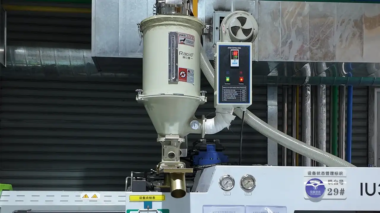
Trocknungsprotokoll – Die unverzichtbare Grundlage
Die Esterbindungen von PET unterliegen bei Vorhandensein von Feuchtigkeit bei Verarbeitungstemperaturen einer hydrolytischen Kettenspaltung. Im Gegensatz zu ABS (bei dem Feuchtigkeit zwar zu einer Ausbreitung der Oberflächenstruktur führt, jedoch nur begrenzte strukturelle Schäden verursacht) oder PC (bei dem der Abbau zwar erheblich ist, sich aber teilweise wieder rückgängig machen lässt) ist die PET-Hydrolyse unter Produktionsbedingungen im Wesentlichen irreversibel – die Verringerung des Molekulargewichts führt direkt zu einer Verringerung der Zugfestigkeit, der Schlagzähigkeit und der Viskosität, wobei keine nachfolgende Wärmebehandlung in der Lage ist, die ursprüngliche Kettenlänge wiederherzustellen.
| Parameter | Ungefülltes PET | GF-PET | PETG | PET-Regranulat |
|---|---|---|---|---|
| Trocknertyp | Entfeuchtungstrichter (Taupunkt ≤ −40 °C) | Dasselbe | Dasselbe | Dasselbe |
| Temperatur | 160–170 °C | 160–170 °C | 65–75 °C | 150–160 °C |
| Dauer | 4–6 Stunden | 4–6 Stunden | 2–3 Stunden | 4–5 Stunden |
| Zielfeuchte | < 0,02 % | < 0,02 % | < 0,05 % | < 0,02 % |
| Überprüfung | Karl-Fischer-Gerät oder Feuchtigkeitsanalysator | Karl Fischer | Feuchtigkeitsmessgerät | Feuchtigkeitsmessgerät |
| Maximaler Nachmahlanteil | 10–15 % | 10 % | 20 % | — |
Dimuds Standard: Vor jedem Produktionslauf von PET in technischer Qualität erfolgt eine Überprüfung mittels Karl-Fischer-Titration. Bei allen anderen PET-Programmen erfolgt eine Überprüfung mittels Feuchtigkeitsanalysator. Dieser Schritt wird im Prozesskontrollplan dokumentiert und im Chargenqualitätsbericht festgehalten.
Zylinder- und Schmelztemperatur
| Zone | Ungefülltes PET | 30% GF-PET | FR-PET | Anmerkungen |
|---|---|---|---|---|
| Rückseite (Eingabe) | 240–255 °C | 250–265 °C | 255–270 °C | Kontrollierter Einlass; keine Kaltzonen, die zu Verstopfungen durch Feststoffe führen könnten |
| Mittel (Kompression) | 255–275 °C | 265–285 °C | 270–285 °C | Primäre Schmelzzone; Homogenitätsziel |
| Vorderseite (Messung) | 265–285 °C | 270–290 °C | 275–290 °C | Endschmelztemperatur; IV- und Viskositätskalibrierung |
| Düse | 255–275 °C | 265–280 °C | 265–280 °C | Düse mit offener Spitze empfohlen; umgekehrte Konusform für Sorten, bei denen es leicht zum Tropfen kommt |
Obergrenze für den Abbau: PET zersetzt sich bei Temperaturen über 290–300 °C (ungefüllt) bzw. 300–310 °C (GF-PET), wobei Acetaldehyd freigesetzt wird und es zu Vergilbung, einer Verringerung des Molekulargewichts sowie zur Bildung von Abgasen kommt. Die Verweildauer im Zylinder muss so kurz wie möglich gehalten werden – Dimud gibt für jede PET-Maschinenkonfiguration eine maximale Verweildauer vor.
Formtemperatur – Die Variable zur Steuerung der Kristallinität
Dieser Parameter hat den größten Einfluss darauf, ob ein PET-Bauteil als technische Komponente funktioniert oder im Einsatz versagt. Ausführliche Hinweise zum Kristallinitätsmanagement finden Sie in Abschnitt 6.
- Niedrige Formtemperatur (10–30 °C): Schockkühlung; amorphes PET; optisch klar; niedrige HDT (65–85 °C); erhöhtes Risiko für Schrumpfung und Verzug. Nur für PETG und transparente Verpackungsanwendungen geeignet.
- Hohe Formtemperatur (120–150 °C): Kontrollierte Kristallisation; teilkristallines PET; opak/weiß; hoher HDT-Wert (220–240 °C mit Glasfaser); Dimensionsstabilität. Für alle PET-Komponentenprogramme im Bereich Ingenieurwesen erforderlich.
Um eine Formtemperatur von 120–150 °C zu erreichen und aufrechtzuerhalten, ist Folgendes erforderlich: Temperaturregler für unter Druck stehendes Heißwasser oder Öl — Herkömmliches Formkühlwasser kann diesen Bereich nicht abdecken. Die GF-PET-Programme von Dimud sind serienmäßig mit speziellen Öltemperaturreglern mit einer Genauigkeit von ±2 °C ausgestattet.
Einspritzgeschwindigkeit und -druck
Die moderate Schmelzviskosität von PET (niedriger als bei PC, höher als bei PP) erfordert eine gezielte Steuerung der Einspritzparameter:
- Einspritzdruck: 80–130 MPa für ungefülltes PET; 120–160 MPa für 30–45% GF-PET
- Haltedruck: 50–70% des Einspritzdrucks; eine verlängerte Haltezeit ist entscheidend für die Maßhaltigkeit bei halbkristallinen Programmen
- Gegendruck: 5–10 MPa — sehr gering; PET reagiert empfindlich auf Scherwärme bei hohem Gegendruck, insbesondere bei GF-Typen, bei denen sich Faserbruch und Wärmeentwicklung gegenseitig verstärken
- Einspritzgeschwindigkeit: Mäßig – eine zu schnelle Befüllung führt zu übermäßiger Scherbeanspruchung am Anguss (Schwäche an der Schweißnaht, Probleme bei der Faserorientierung bei GF-Typen); eine zu langsame Befüllung führt zu vorzeitigem Erstarren
Häufige Mängel und Abhilfemaßnahmen
| Defekt | Grundlegende Ursache | Korrekturmaßnahme |
|---|---|---|
| Silberne Streifen / Schleier | Feuchtigkeit > 0,021 TP3T; Hydrolyse | Trocknungszeit verlängern; Taupunkt überprüfen; Dichtheit des Trichters prüfen |
| Teilweise Sprödigkeit / geringe Belastung | Hydrolytische IV-Reduktion; Überhitzung | Trocknung überprüfen; Trommeltemperatur senken; Verweilzeit überprüfen |
| Verzug (flache GF-PET-Teile) | Anisotrope Schrumpfung; ungleichmäßige Füllung | Position des Ausgleichsventils einstellen; Füllmuster anpassen; Kühlung optimieren |
| Einfallstellen | Unzureichender Halte-Druck/Haltezeit bei dicken Abschnitten | Den Anpressdruck erhöhen; dicke Stellen aushöhlen |
| Geringer Oberflächenglanz | Formtemperatur zu niedrig; vorzeitiges Abkühlen | Formtemperatur erhöhen; Stabilität des Temperaturreglers überprüfen |
| Weiße / undurchsichtige Bereiche in transparenten Teilen | Unbeabsichtigte Kristallisation (Formtemperatur für PETG zu hoch) | Temperatur der unteren Form senken; Temperaturregler überprüfen |
| Schweißnähte (schwach) | Niedrige Schmelztemperatur; ungünstige Angussposition | Schmelztemperatur erhöhen; Anguss neu positionieren; Formtemperatur erhöhen |
| Kurzer Schlag | GF-Typ mit hoher Viskosität; unzureichender Druck | Einspritzdruck erhöhen; Anguss vergrößern; Zylindertemperatur erhöhen |
| Gelbliche Verfärbung | Thermischer Abbau; lange Verweildauer | Zylindertemperatur senken; spülen; Zylindergröße an das Schussvolumen anpassen |
| Freiliegende Faseroberfläche (GF-Teile) | Formtemperatur zu niedrig; abrasiver Materialfluss am Anguss | Formtemperatur erhöhen; Scherkräfte am Anguss verringern; gehärtete Angusseinsätze verwenden |
Überlegungen zur Formgestaltung von PET-Kunststoffbauteilen
Torentwurf
Die mäßige bis hohe Schmelzviskosität von PET-Kunststoff und sein teilkristallines Erstarrungsverhalten führen zu spezifischen Anforderungen an die Angusskanäle, die sich von denen amorpher Polymere unterscheiden:
- U-Boot-(Tunnel-)Tore: Geeignet für ungefüllte PET- und Low-GF-Typen; Angussdurchmesser mindestens 1,0–1,5 mm, um ein vorzeitiges Abkühlen während der Haltephase zu verhindern.
- Rand- und Fansektoren: Bevorzugt für flache GF-PET-Teile, bei denen die Füllbalance und die Steuerung der Faserorientierung entscheidend sind – breitere Füllfronten reduzieren anisotrope Orientierungseffekte.
- Heißkanal-Nadelverschlüsse: Empfohlen für PET-Serienfertigungsprogramme mit hohem Volumen bei Dimud. Eine präzise Steuerung des Ventilanschluss-Timings regelt den Übergang von der Füll- zur Nachfüllphase, reduziert das „Gate Blush“-Phänomen und verhindert Kaltkanäle, die bei feuchtigkeitsempfindlichem PET zu Qualitätsproblemen beim Mahlgut führen. Das Material der Anschlus spitze muss für GF-PET aufgrund des abrasiven Faserstroms gehärtet sein (H13 oder gleichwertig).
- Direkte (Anguss-)Angüsse: Wird für große GF-PET-Strukturteile mit einer einzigen Formkammer verwendet, bei denen die Angussgröße maximiert werden kann, um Scherkräfte und Faserbruch zu reduzieren.
Länge der Angussbrücken: maximal 0,5–1,0 mm. Überlange Angussbrücken sind eine häufige Ursache für übermäßige Scherwärmeentwicklung und Faserschäden bei GF-PET-Verfahren.
Stahlauswahl
PET-Programme stellen zwei spezifische Anforderungen an die Auswahl des Werkzeugstahls, die sich von denen für Standard-ABS- oder PS-Werkzeuge unterscheiden:
| Zustand | Stahlbedarf | Begründung |
|---|---|---|
| Ungefüllte / PETG-Programme | P20 oder 718H vorgehärtet | Standardmäßige strukturelle und transparente Anwendungen |
| GF-PET (15–30%) | H13-gehärtete (48–52 HRC) + nitrierte Gusskanaleinsätze | Glasfasern führen zu einem beschleunigten abrasiven Verschleiß an den Anguss- und Formhohlraumoberflächen |
| GF-PET (30–45%) | H13- oder D2-gehärtete + PVD-beschichtete Schiebereinsätze | Ein hoher Ballaststoffanteil erfordert höchste Verschleißfestigkeit |
| PET / PETG in medizinischer Qualität | 420SS oder S136 Edelstahl | Korrosionsbeständigkeit gegenüber Reinigungsmitteln; Polierbarkeit für optische/kosmetische Oberflächen |
P20 ist für GF-PET-Programme mit einem Glasfaseranteil von mehr als 15% nicht geeignet. Der Verschleiß des Angusskanals bei GF-PET führt zu fortschreitenden Maßänderungen und zur Bildung von Angussresten, die sich nicht durch eine Prozessanpassung beheben lassen – sondern nur durch den Austausch des Angusskanaleinsatzes. Dimud schreibt bei allen GF-PET-Programmen ab 15% GF standardmäßig Angusskanaleinsätze aus gehärtetem Stahl vor, wobei für Werkzeuge mit hohem Produktionsvolumen austauschbare Einsätze vorgesehen sind.
Auslegung des Kühlsystems
Aufgrund der hohen Anforderungen an die Formtemperatur bei PET (120–150 °C für teilkristalline technische Kunststoffe) muss das Formkühlsystem als Temperaturerhaltungssystem sondern vielmehr ein System zur Wärmeableitung. Das Ziel ist eine gleichmäßige Wärmeverteilung über die gesamte Oberfläche des Hohlraums, nicht die maximale Wärmeabfuhr:
- Die Auslegung des Heiz-/Kühlkreislaufs zielt auf eine Gleichmäßigkeit von ±3 °C über die gesamte Hohlraumoberfläche bei stationärer Betriebstemperatur ab.
- Öltemperaturregler gehören bei Dimud zur Standardausstattung für GF-PET-Programme (Temperaturbereich 120–160 °C, Stabilität ±2 °C)
- Konforme Heiz- und Kühlkreisläufe kommen bei komplexen Oberflächengeometrien zum Einsatz, bei denen geradlinige Kanäle nicht die erforderliche Temperaturgleichmäßigkeit gewährleisten können.
- Protokoll für den Formstart: Die Form vor dem ersten Schuss auf die Solltemperatur vorheizen – bei Kaltstarts an Hochtemperatur-PET-Formen entstehen in den ersten 15–30 Schüssen Teile mit Maßabweichungen, während sich die Form auf Temperatur bringt
Entlüftung
PET setzt bei Verarbeitungstemperaturen Acetaldehyd und andere flüchtige Nebenprodukte frei. Eine ausreichende Entlüftung ist unerlässlich:
- Entlüftungstiefe: 0,025–0,04 mm bei ungefülltem PET; 0,03–0,05 mm bei GF-Typen (ein höherer Fülldruck erfordert tiefere Entlüftungen)
- Lüftungsspalt: 3–5 mm
- Entlüftung an der peripheren Trennfuge sowie Entlüftung des Auswerferstiftabstands an allen tiefen Strukturen
- Vakuumgestützte Entlüftung bei der Herstellung von optischem Präzisions-PETG zur Erzielung von Trübungswerten < 1,0%
Auswurfsystem
Die moderate Zähigkeit von PET (geringer als bei ABS/PC, höher als bei ungefüllten, spröden Polymeren) in Verbindung mit seiner Neigung zum Anhaften bei erhöhten Formtemperaturen führt zu besonderen Anforderungen an den Auswurf:
- Großzügige Entformungswinkel (1,5°–3° pro Seite) sind wichtiger als bei ABS, da die Oberflächenrauheit von GF-PET bei erhöhten Formtemperaturen die Auswurfkraft erhöht.
- Bei zylindrischen und rohrförmigen GF-PET-Teilen wird vorzugsweise ein Abstreifer oder ein Hülsenauswerfer verwendet
- Auswerfstifte müssen bei Steckverbinderteilen, bei denen für alle Außenflächen Maßtoleranzen gelten, in nicht optisch relevanten Bereichen angeordnet sein.
- Für flache GF-PET-Teile mit engen Ebenheitstoleranzen werden Kühlvorrichtungen nach dem Auswerfen empfohlen – die Teile befinden sich beim Auswerfen noch oberhalb ihrer Glasübergangstemperatur und können sich ohne Unterstützung durch die Vorrichtung unter ihrem Eigengewicht verformen
Steuerung der Kristallinität: Die Variable, die die Leistungsfähigkeit von PET-Bauteilen bestimmt

Für Ingenieure, die noch keine Erfahrung mit dem PET-Spritzguss haben, ist kein Abschnitt dieses Leitfadens wichtiger als dieser. Die Steuerung der Kristallinität ist der technische Aspekt, der hochleistungsfähige PET-Bauteile von verzerrten, maßabweichenden oder thermisch unzureichenden Teilen unterscheidet – und genau in diesem Bereich besteht die größte Wissenslücke.
Warum die Kristallinität wichtig ist
Aufgrund der teilkristallinen Beschaffenheit von PET werden seine Eigenschaften nicht allein durch die Zusammensetzung bestimmt – sie hängen entscheidend davon ab, in welchem Umfang sich das Polymer während des Abkühlens zu kristallinen Domänen organisiert hat. Die praktischen Konsequenzen:
| Kristallinitätsgrad | Optisches Erscheinungsbild | HDT | Formstabilität | Typische Anwendung |
|---|---|---|---|---|
| < 5% (amorph) | Optisch klar | 65–70 °C | Schlecht (Kriechen unter Last) | Verpackungen, PETG-Teile |
| 5–20% (teilkristallin) | Trüb / durchscheinend | 70–120 °C | Mäßig | Übergangsbereich; bei technischen Bauteilen vermeiden |
| 20–35% (teilkristallin, Ziel) | Deckendes Weiß / Cremefarben | 200–240 °C (mit GF) | Ausgezeichnet | Steckverbinder für die Automobilindustrie, Elektronikbauteile |
| > 35% (überkristallisiert) | Undurchsichtig, spröde | Sehr hoch | Kann zu Sprödigkeit führen | Zu vermeiden; tritt bei zu langsamer Abkühlung auf |
Wie man die Kristallinität durch die Formtemperatur steuert
Der wichtigste Hebel zur Steuerung der Kristallinität beim Spritzgießen ist Formtemperatur:
- Unter 80 °C: Die Kristallisation wird unterdrückt; überwiegend amorphe Anteile (ungeeignet für technische Anwendungen, die einen hohen HDT-Wert erfordern)
- 80–110 °C: Teilweise, ungleichmäßige Kristallisation; unterschiedliche Eigenschaften zwischen den Kavitäten und von Schuss zu Schuss – der ungünstigste Bereich für technische Bauteile
- 120–140 °C: Optimaler Temperaturbereich für technisches PET. Nukleierungsmittel in Spritzguss-Typen sorgen für eine schnelle, gleichmäßige Kristallisation innerhalb der Zykluszeit. Die Bauteile erreichen die angestrebte Kristallinität (25–35%) mit gleichbleibenden Eigenschaften.
- Über 150 °C: Gefahr der Überkristallisation bei Dünnschnitten; die Zykluszeit verlängert sich, ohne dass sich die Eigenschaften nennenswert verbessern
Die Folge: Bei PET-Verarbeitungsprozessen kann kein normales Formkühlwasser (in der Regel 15–25 °C) verwendet werden. Heißwasser- oder Öl-Temperaturregelgeräte sind eine unverzichtbare Investition und keine Option.
Glühen nach dem Formpressen für maximale Kristallinität
Für Anwendungen, die höchste Hitzebeständigkeit und Formstabilität erfordern – beispielsweise Automobilkomponenten, die für den Dauerbetrieb bei Temperaturen über 200 °C ausgelegt sind, oder Präzisionssteckverbinder mit engem Pin-Abstand – sorgt das Glühen nach dem Spritzgießen dafür, dass die Kristallisation nach dem Entformen abgeschlossen wird:
- Temperatur: 130–150 °C in einem Umluftofen
- Dauer: 30 Minuten bis 2 Stunden, je nach Wandstärke und angestrebter Kristallinität
- Spannvorrichtungen: Die Teile werden in Maßhaltigkeitsvorrichtungen geglüht, um Verformungen während der abschließenden Kristallisationsphase zu verhindern
- Ergebnis: Die Kristallinität steigt von 25–30% (im Formzustand) auf 32–40% (nach dem Glühen); die HDT verbessert sich um 5–15 °C; die Maßschrumpfung ist abgeschlossen, wodurch sich die langfristige Maßstabilität verbessert
Dimud führt bei allen GF-PET-Programmen für Automobilsteckverbinder und Präzisionselektronik, bei denen die Betriebstemperaturen 180 °C überschreiten, standardmäßig ein Nachformglühen als sekundären Arbeitsschritt durch.
Anwendungen in der Industrie
Automobilindustrie
Die Automobilbranche ist der Anwendungsbereich mit dem höchsten Wert für PET-Kunststoffe in Ingenieursqualität. Dies ist auf die Kombination aus HDT-Werten (220–235 °C bei den 30% GF-Typen), chemischer Beständigkeit gegenüber Kraftstoffen und Schmierstoffen, Maßgenauigkeit sowie der Verfügbarkeit der Brandschutzklasse UL 94 V-0 für elektrische Bauteile zurückzuführen.
Präzisionssteckverbinder (30–45% GF-PET): PET-Kunststoff dominiert den Markt für elektrische Steckverbinder in der Automobilindustrie – die hohe HDT, die stabilen dielektrischen Eigenschaften und die Maßgenauigkeit von GF-PET ermöglichen die Herstellung von Steckverbindergehäusen, bei denen die Toleranzen des Stiftabstands (typischerweise ±0,05–0,10 mm) über den gesamten Betriebstemperaturbereich des Fahrzeugs hinweg eingehalten werden. Die bei Dimud aus 30% GF-PET geformten Steckverbindergehäuse sind hinsichtlich ihrer Maßhaltigkeit gemäß den USCAR-2-Leistungsstandards für Steckverbinder validiert und verfügen über eine PPAP-Level-3-Dokumentation.
Komponenten für EV-Batteriemodule (FR-PET, UL 94 V-0): Der rasante Übergang zu Elektrofahrzeugen hat zu einer starken Nachfrage nach FR-PET für Zellabstandshalter in Batteriemodulen, Isolatoren für Sammelschienen und Gehäuse für Hochspannungssteckverbinder geführt. FR-PET der Klasse V-0 vereint Flammwidrigkeit, thermische Stabilität bei Dauerbetriebstemperaturen von Batterien (bis zu 120–130 °C) und Maßgenauigkeit – Eigenschaften, die Alternativen aus PBT und PA bei vergleichbaren Kosten nur schwer erreichen können.
Sensorgehäuse und Halterungskomponenten für den Motorraum (30% GF-PET): Temperatursensoren, Druckwandler und Gehäuse für Füllstandssensoren erfordern Werkstoffe, die bei den unter der Motorhaube herrschenden Temperaturen (80–130 °C im Dauerbetrieb, 150 °C Spitzenwert) ihre Formstabilität bewahren und gleichzeitig dem Kontakt mit Kraftstoff, Öl und Kühlmittel standhalten. 30% GF-PET erfüllt alle drei Anforderungen gleichzeitig.
Komponenten des Kraftstoffsystems (chemikalienbeständiges, ungefülltes PET): Dank seiner hervorragenden Beständigkeit gegenüber aromatischen und aliphatischen Kohlenwasserstoffen eignet sich PET für Bauteile, die mit Kraftstoff in Berührung kommen, darunter Filtergehäuse, Ventilkörper und Durchflussregelungskomponenten.
Unterhaltungselektronik
Die Einsatzbereiche von PET-Kunststoff in der Elektronik konzentrieren sich auf Präzisionssteckverbindergehäuse, strukturelle Halterungen und Bauteile, bei denen die Kombination aus Formstabilität, dielektrischen Eigenschaften und Kosteneffizienz ausschlaggebend für die Spezifikation ist.
SMD-Steckverbindergehäuse und Buchsenkörper (30% GF-PET / FR-PET): Steckverbinder für oberflächenmontierte Bauteile, Board-to-Board-Steckverbinder und I/O-Sockel in der Unterhaltungselektronik und in Industriegeräten. GF-PET bietet die für die Bestückung mit SMD-Bauteilen erforderliche Maßgenauigkeit (Toleranzen beim Pin-Abstand von ±0,05 mm bei Steckverbindern mit 0,5-mm-Rastermaß) in Kombination mit Reflow-Lötbarkeit bei bestimmten Hochtemperatur-PET-Typen, die für Reflow-Spitzentemperaturen von 260 °C ausgelegt sind.
Halterungen für Leiterplatten (30% GF-PET): Versteifungshalterungen, Abstandshalter und Führungsschienen für Leiterplattenbaugruppen in Computer- und Kommunikationsgeräten. Der hohe Biegemodul von 30% GF-PET (9.000–11.000 MPa) sorgt für ein im Vergleich zu Alternativen bei gleicher Kostenhöhe überlegenes Verhältnis von Steifigkeit zu Gewicht.
ESD-geschützte Schalen und Handhabungsvorrichtungen (ESD-PET): PET mit Kohlenstoff- oder Edelstahlfaserverstärkung für Handhabungsschalen für Halbleiterkomponenten, Waferträger und Montagevorrichtungen für Elektronik, bei denen gleichzeitig eine kontrollierte Oberflächenwiderstandsfähigkeit (10⁶–10¹¹ Ω/sq) und thermische Stabilität bei PCB-Aushärtungstemperaturen (125–150 °C) erforderlich sind.
Medizinische Geräte
PET-Kunststoff und sein Copolymer PETG spielen bei der Herstellung medizinischer Produkte eine klar definierte Rolle, bei der ihre optische Transparenz, ihre chemische Verträglichkeit und ihre Sterilisierbarkeit zum Tragen kommen.
Transparente Gehäuse für medizinische Geräte und Sichtfenster (PETG): Die dauerhaft amorphe Transparenz von PETG, seine chemische Beständigkeit gegenüber gängigen Desinfektionsmitteln im Krankenhausbereich (IPA, quartäre Ammoniumverbindungen) sowie seine Biokompatibilität (zertifizierte Qualitäten gemäß USP Klasse VI) machen es zum Material der ersten Wahl für transparente Geräteblenden, Sichtfenster zur Probeninspektion und Komponenten für diagnostische Tests. Im Gegensatz zu PC neigt PETG bei Kontakt mit den meisten in medizinischen Umgebungen verwendeten Desinfektionslösungen nicht zur ESC-Rissbildung.
Medizinische Verpackungen und Sterilisationsschalen (unbefüllt / PET in medizinischer Qualität): Die Eignung von PET für die EO- und Gamma-Sterilisation in Verbindung mit der FDA-Zulassung für den Kontakt mit Lebensmitteln und Arzneimitteln macht es zum Standardmaterial für Sterilisationsverpackungen, Instrumentenschalen und Behälter für Einwegprodukte. Die medizinischen PET-Programme von Dimud basieren standardmäßig auf Verfahren, bei denen ausschließlich Neuware verwendet wird, und gewährleisten eine dokumentierte Rückverfolgbarkeit der Chargen.
Komponenten der mikrofluidischen Vorrichtung (PETG): Dank seiner optischen Klarheit, der geringen Autofluoreszenz und der Eignung für thermische und lösungsmittelbasierte Verklebungen ist PETG eine überzeugende Alternative zu PC für Substrate von mikrofluidischen Diagnosechips in Point-of-Care-Anwendungen.
Bei Dimud werden medizinische PET-Programme durch unsere Kunststoffspritzguss-Dienstleistung Infrastruktur – einschließlich sauberer Produktionszellen, dokumentierter Rückverfolgbarkeit der Materialien und Chargenzertifikaten als Standardlieferumfang.
Robotik und Energiespeicherung
Komponenten für Roboter-Befestigungsvorrichtungen (30% GF-PET): Präzisionsmontagevorrichtungen, Prüfvorrichtungen und Halterungen in robotergestützten Fertigungslinien. Die Kombination aus hoher Steifigkeit (Biegemodul > 9.000 MPa), Maßhaltigkeit und Bearbeitbarkeit für Nachbearbeitungsschritte macht 30% GF-PET zu einer kostengünstigen Alternative zu Aluminiumvorrichtungen bei Produktionsmengen von über 500 Einheiten.
Batteriezellhalter und Modulkomponenten (FR-PET, V-0): Zellabstandshalter, Modulrahmen und isolierende Trennelemente in Lithium-Ionen-Akkupacks für Energiespeichersysteme und Roboterantriebsplattformen. FR-PET V-0 erfüllt die gleichzeitigen Anforderungen an Flammwidrigkeit, Dimensionsstabilität bei Temperaturwechselbeanspruchung (−20 °C bis +130 °C) und Beständigkeit gegenüber elektrolytnahen Umgebungen.
Präzisionsgehäuse für Drehgeber und Sensoren (30% GF-PET): Gehäuse für Encoderräder, Halterungen für Drehsensoren und Halterungen für optische Sensoren in Servomotorbaugruppen. Die Kombination aus engen Maßtoleranzen, die mit 30% GF-PET (Schrumpfung 0,2–0,5% in Fließrichtung) erreichbar sind, und einer hohen HDT macht dieses Material gegenüber PA66 in Anwendungen vorteilhaft, bei denen Maßänderungen unter thermischer Belastung minimiert werden müssen.
PET-Kunststoff im Vergleich zu anderen Materialien
| Eigentum | 30% GF-PET | 30% GF-PBT | 30% GF-PA66 | 30% GF-PP | Nicht besetzter PC |
|---|---|---|---|---|---|
| Zugfestigkeit | ★★★★★ | ★★★★☆ | ★★★★★ | ★★★☆☆ | ★★★☆☆ |
| Wärmebeständigkeit (HDT) | ★★★★★ | ★★★★☆ | ★★★★★ | ★★★☆☆ | ★★★★☆ |
| Formstabilität | ★★★★★ | ★★★★☆ | ★★★☆☆ | ★★★☆☆ | ★★★★☆ |
| Chemische Beständigkeit | ★★★★★ | ★★★★★ | ★★★☆☆ | ★★★★★ | ★★★☆☆ |
| Feuchtigkeitsaufnahme | ★★★★★ | ★★★★★ | ★★☆☆☆ | ★★★★★ | ★★★★☆ |
| Dielektrische Eigenschaften | ★★★★★ | ★★★★☆ | ★★★☆☆ | ★★★★☆ | ★★★★☆ |
| Einfache Verarbeitung | ★★★☆☆ | ★★★★☆ | ★★★☆☆ | ★★★★★ | ★★★☆☆ |
| Rohstoffkosten | $$ Mittel | $$ Mittel | $$$ Hoch | $ Niedrig | $$$ Hoch |
| Recycelbarkeit | ★★★★★ (#1) | ★★★☆☆ | ★★☆☆☆ | ★★★★☆ | ★★☆☆☆ |
PET vs. PBT: PBT (Polybutylenterephthalat) und PET haben zwar das gleiche Polyester-Grundgerüst, unterscheiden sich jedoch in der Länge der Glykolsegmente. PBT kristallisiert schneller und bei niedrigeren Formtemperaturen (60–80 °C gegenüber 120–140 °C bei technischem PET), wodurch es sich leichter verarbeiten lässt. PET zeichnet sich durch eine höhere Zugfestigkeit, bessere Dimensionsstabilität und geringere Feuchtigkeitsaufnahme aus. Für Steckverbinder in der Automobilindustrie, die maximale Dimensionsstabilität erfordern, wird PET bevorzugt; für Anwendungen, bei denen kürzere Zykluszeiten und niedrigere Formtemperaturen entscheidend sind, ist PBT oft die praktikablere Wahl. Dimud verarbeitet beide Materialien und berät Sie gerne bei der richtigen Auswahl für spezifische Projekte.
PET im Vergleich zu PA66 (Nylon 66): Beide bieten in Glasfaser-Ausführungen eine hohe Hitzebeständigkeit und sind die dominierenden Werkstoffe bei Steckverbindern für die Automobilindustrie. Die Schwäche von PA66 liegt in der Feuchtigkeitsaufnahme (2,5–3,5% im Gleichgewicht), die zu erheblichen Maßänderungen und Eigenschaftsschwankungen zwischen dem trockenen Formzustand und dem konditionierten Zustand führt. Die Feuchtigkeitsaufnahme von GF-PET (< 0,15%) sorgt für eine hervorragende Dimensionsstabilität in feuchten Umgebungen – ein entscheidender Vorteil für Präzisionssteckverbinderanwendungen, bei denen der Abstand zwischen den Stiften unter allen klimatischen Bedingungen eingehalten werden muss.
PET vs. PP: Standard-PP mit Glasfaserverstärkung bietet eine kostengünstige Alternative für Anwendungen mit geringeren Leistungsanforderungen. Bei Betriebstemperaturen über 120 °C ist der Vorteil von GF-PET hinsichtlich der Wärmeformbeständigkeit (HDT) (220–235 °C gegenüber 130–145 °C bei 30% GF-PP) entscheidend. PP punktet hingegen mit seiner chemischen Beständigkeit gegenüber starken Basen und geringeren Verarbeitungskosten.
Einen umfassenden Überblick darüber, wie sich PET im Vergleich zum gesamten Materialportfolio von Dimud schlägt, finden Sie im Leitfaden zu Spritzgusswerkstoffen.
DFM-Richtlinien für PET-Kunststoffteile
Für ein effektives DFM bei PET-Kunststoffen müssen sowohl die allgemeinen Regeln für die Konstruktion von Spritzgussteilen als auch die PET-spezifischen Aspekte berücksichtigt werden, die sich aus der teilkristallinen Erstarrung und der Glasfaserverstärkung ergeben.
Unter Dimud, unser Produktdesign und DFM-Service prüft jedes PET-Programm, bevor die Werkzeuge festgelegt werden – einschließlich der Empfehlung der geeigneten Materialsorte, der Wanddickenanalyse, der Optimierung der Angussposition und der Vorhersage der anisotropen Schrumpfung.
Wanddicke
Empfohlener Bereich: 1,5–4,0 mm für strukturelles GF-PET; 0,8–2,0 mm für ungefülltes PET in dünnwandigen Anwendungen.
Eine gleichmäßige Wandstärke ist bei PET wichtiger als bei amorphen Polymeren, da die unterschiedliche Kristallinitätsentwicklung in dicken und dünnen Bereichen zu einer ungleichmäßigen Schrumpfung führt. Die 2:1-Regel für das Dickenverhältnis (maximales Verhältnis zwischen dicken und dünnen benachbarten Wänden) wird im GF-PET-DFM-Standard von Dimud strikt angewendet. Abrupte Änderungen der Wandstärke bei GF-PET-Bauteilen führen zusätzlich zu Unterbrechungen der Faserorientierung an den Übergängen, was lokale Schwachstellen verursacht.
Eckenradien
Mindestradius für Innenecken: 0,5 mm. Empfohlen: 1,0 mm oder 25–50% der Wandstärke.
Die relativ geringe Bruchdehnung von GF-PET (2–4% bei 30% GF) führt dazu, dass Spannungskonzentrationen an scharfen Ecken unter mechanischer Belastung ein Risiko für die Bruchauslösung darstellen. Bei Steckverbinderprogrammen – bei denen die Bauteile während ihrer gesamten Lebensdauer Einsteck- und Ausziehkräften ausgesetzt sind – müssen alle Innenecken einen Radius von mindestens 0,5 mm aufweisen; 1,0 mm ist die Standardempfehlung von Dimud.
Rippen- und Vorsprungsdesign
- Rippenstärke: 50–60% der Nennwand — Es gilt dieselbe Regel wie bei amorphen Polymeren, doch aufgrund des hohen Elastizitätsmoduls von GF-PET sind Einfallstellen an dicken Stegen optisch deutlich erkennbar und maßlich signifikant.
- Außendurchmesser des Ansatzes: maximal 2× Nennwandstärke; hohlgebohrte Ansätze bei Profilen mit einer Tiefe von mehr als 8 mm
- Übergänge zwischen Wulst und Wand: abgerundet (mindestens 0,5 mm; 1,0 mm empfohlen)
- Ausrichtung der Rippen: Bei GF-PET weisen Rippen, die in Richtung der primären Füllrichtung ausgerichtet sind, eine bessere Faserausrichtung und eine höhere Steifigkeit auf; Rippen, die senkrecht zur Füllrichtung stehen, sind schwächer und neigen eher zu Einfallstellen.
Entwurfswinkel
- Standardoberflächen: 1°–1,5° mindestens pro Seite (höher als bei amorphen Polymeren aufgrund erhöhter Formtemperaturen)
- Strukturierte Oberflächen: 1° pro 0,025 mm Strukturtiefe hinzufügen
- Tiefe Taschen und Durchgangsbohrungen: mindestens 2° für einen zuverlässigen Auswurf von kristallinem PET aus polierten Stahloberflächen bei einer Formtemperatur von 130 °C+
Erreichbare Toleranzen
Die anisotrope Schrumpfung von GF-PET erfordert Toleranzvorgaben, die den Unterschieden zwischen Längs- und Querrichtung Rechnung tragen:
- Strömungsrichtung: ±0,05–0,10 mm (fest; geringe Schrumpfung 0,2–0,51 TP3T)
- Querrichtung: ±0,10–0,20 mm (breiter; höhere Schrumpfung 0,6–1,21 TP3T)
- Bei Steckverbinderprogrammen mit symmetrischen Pin-Anordnungen: Die von Moldflow prognostizierte Schrumpfungsdifferenz muss bei den Kavitätenabmessungen für jede Pin-Position berücksichtigt werden – ein Standardbestandteil der GF-PET-Steckverbinder-Werkzeugprogramme von Dimud.
Qualitätsstandards, Compliance und Nachhaltigkeit
Qualitätsmanagement bei Dimud
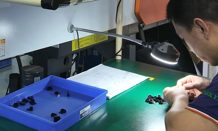
- An die IATF 16949 angepasste Verfahren für PET-Programme im Automobilbereich: PPAP Stufe 3, FMEA, Kontrollpläne, statistische Prozesskontrolle (SPC) für kritische Steckverbinderabmessungen, Karl-Fischer-Feuchtigkeitsprotokolle als standardmäßige Chargendokumentation.
- ISO 13485-konforme Prozesssteuerung Für medizinisches PET/PETG: Rückverfolgbarkeit der Harzchargen, Konformitätsbescheinigung (CoC) pro Charge, Unterlagen zur Verträglichkeit mit Desinfektionsmitteln auf Anfrage.
- Maßprüfung mit Koordinatenmessgerät (CMM) mit einem Cpk-Wert von ≥ 1,67 bei kritischen Maßen; vollständige Pin-zu-Pin-Zuordnung bei Steckverbinderprogrammen.
- Prüfung von Probekörpern gemäß UL 94 V-0 für alle FR-PET-Programme mit Unterlagen für die Einreichung von UL-Unterlagen durch Kunden.
- Überprüfung nach dem Formglühen: Maßprüfung vor und nach dem Glühen, um sicherzustellen, dass der Schrumpfvorgang bei Projekten im Automobilbereich und in der Präzisionselektronik abgeschlossen ist.
Zusammenfassung zur Einhaltung gesetzlicher Vorschriften
| Anwendung | Standard | PET-Qualität | Zentrale Anforderung |
|---|---|---|---|
| Kontakt mit Lebensmitteln | FDA 21 CFR 177.1630, EU 10/2011 | PET/PETG in Lebensmittelqualität | Einhaltung der Vorschriften für Zusatzstoffe; IV-Überprüfung |
| Komponenten für Medizinprodukte | ISO 10993-1, USP Klasse VI | PETG/PET in medizinischer Qualität | Biokompatibilität; Rückverfolgbarkeit der Chargen |
| Elektroniksteckverbinder | UL 94 V-0, IEC 60335 | FR-PET | Brandschutzklasse; Reflow-Kompatibilität |
| Steckverbinder für die Automobilindustrie | USCAR-2, IATF 16949 | 30–45% GF-PET | Maßhaltigkeit; PPAP-Stufe 3 |
| Komponenten für Elektrofahrzeug-Batterien | UL 94 V-0, IEC 62133 | FR-PET | Flammbeständigkeit; Temperaturwechselbeanspruchung |
| Produkte für den EU-Markt | RoHS 2011/65/EU, REACH | Alle Klassenstufen | Konformitätserklärung |
PETs Vorreiterrolle im Bereich Nachhaltigkeit
PET-Kunststoff trägt Recycling-Code #1 — der Kunststoff mit dem höchsten Recyclinganteil im weltweiten Post-Consumer-Kreislauf, von dem weltweit jährlich etwa 2,2 Millionen Tonnen recycelt werden. Für Ingenieure, die Produkte unter Berücksichtigung von Nachhaltigkeitskriterien entwickeln:
- rPET aus Altverpackungen: Recyceltes PET ist im Handel sowohl in ungefüllten als auch in glasfaserverstärkten Ausführungen für nicht kritische technische Anwendungen erhältlich. Dimud kann zertifiziertes rPET-Granulat mit Nachweisen zum Recyclinganteil für Kunden beschaffen, die Nachhaltigkeitsangaben auf Produktebene machen.
- Rezyklat im geschlossenen Kreislauf: Dimud recycelt 100% PET-Produktionsabfälle über qualifizierte Mahlgutkanäle in festgelegten Anteilen (maximal 10–15% Mahlgut in technischen Anwendungen).
- CO₂-Fußabdruck: Die im Vergleich zu technischen Kunststoffen wie PPS oder PEI (330–370 °C) niedrigere Verarbeitungstemperatur von PET (270–290 °C) führt zu einem geringeren Energieverbrauch pro Kilogramm Formteil.
- Recyclinggerechtes Design: Der DFM-Service von Dimud umfasst standardmäßig eine Bewertung der Recyclingfähigkeit als Option für Kunden, die Anforderungen an die Nachhaltigkeit ihrer Produkte am Ende ihrer Lebensdauer stellen.
Dimuds Kompetenzen im Bereich des PET-Kunststoffspritzgusses
Dimud bietet PET-Kunststoffspritzguss als Teil eines vollständig integrierten Fertigungssystems an – drei aufeinander abgestimmte Werke, die die Formenentwicklung abdecken, CNC-Bearbeitung, sowie Elektronikmontage, wobei das Unternehmen Kunden in Europa, Nordamerika und dem Nahen Osten bedient.
| Servicephase | Dimud-Fähigkeit | Kundenvorteil |
|---|---|---|
| DFM- und Qualitätsprüfung | Materialempfehlung (PET vs. PBT vs. PA66); Analyse der anisotropen Schrumpfung; Simulation der Glasfaserorientierung; Festlegung der Zielkristallinität | Beseitigen Sie die häufigsten GF-PET-Fehlerursachen noch vor der Werkzeugherstellung |
| Schnelles Prototyping | SLA/SLS-Simulationsmodelle + Aluminium-Soft-Tools aus GF-PET oder PETG | Entwicklungsmuster innerhalb von 10–15 Arbeitstagen |
| Formenbau | H13/D2-Hartstahl mit austauschbaren Anguss-Einsätzen für GF-Typen; Heißkanal-Nadelverschluss; von Moldflow vorab validiert; kompatibel mit Öltemperaturregler | Serienreife GF-PET-Formwerkzeuge mit garantierter Schusszahl |
| Serienformung | Maschinen von 50 t bis 1.600 t; Öltemperaturregelung 120–160 °C; Karl-Fischer-Feuchtigkeitsprüfung; saubere Kammern für medizinische Anwendungen | Herstellung von PET in technischer Qualität – vom Pilotbetrieb bis zur Serienproduktion |
| Nachbearbeitung | Präzisionsglühen mit Maßvorrichtungen; Tampondruck; Ultraschallschweißen; Montage | Komplette Baugruppen einschließlich nachgelagerter Maßprüfung |
| Qualitätsdokumentation | PPAP, CoC, Karl-Fischer-Feuchtigkeitsmessprotokolle, CMM-Steckerbelegung, UL-94-Zertifikate, SPC-Diagramme | Audit-fähig für Tier-1-Zulieferer der Automobilindustrie, OEMs der Medizintechnikbranche und Kunden aus der Elektronikbranche |
| Lieferkette | Beschaffung von Harzen von Ticona/DuPont/DSM/Celanese; Überprüfung eingehender Chargen IV; DDP-Logistik | Rückverfolgbarkeit des Kunststoffs vom Hersteller bis zum fertigen Bauteil |
Um unser gesamtes Angebot an Materialien und Leistungen zu entdecken, besuchen Sie die Spritzgießmaterialien Bibliothek auf unserer Website.
Häufig gestellte Fragen
PET (Polyethylenterephthalat) und PBT (Polybutylenterephthalat) haben zwar die gleiche chemische Grundstruktur als Polyester, unterscheiden sich jedoch im Glykolsegment – bei PET ist es Ethylenglykol, bei PBT Butylenglykol. PBT kristallisiert schneller und vollständiger bei niedrigeren Formtemperaturen (60–80 °C), wodurch es einfacher zu verarbeiten ist und geringere Anforderungen an die Temperaturregelungstechnik stellt. PET zeichnet sich durch eine höhere Zugfestigkeit, geringere Feuchtigkeitsaufnahme, bessere Dimensionsstabilität in feuchten Umgebungen und ein besseres Nachhaltigkeitsprofil aus (Recyclingcode #1-Infrastruktur). Für Präzisionssteckverbinder in der Automobilindustrie, bei denen Maßhaltigkeit unter allen klimatischen Bedingungen die wichtigste Anforderung ist, empfiehlt Dimud standardmäßig 30% GF-PET anstelle von PBT. Für Anwendungen, bei denen einfache Verarbeitung und kürzere Zykluszeiten im Vordergrund stehen, kann PBT die praktikablere Wahl sein.
Ja – allerdings nur bei glasfaserverstärkten Typen mit kontrollierter Kristallisation. Ungefülltes PET weist eine Wärmeformbeständigkeit von nur 65–85 °C auf, was für die meisten Anwendungen im Automobilbereich nicht ausreicht. 30% GF-PET erreicht eine Wärmeformbeständigkeit (HDT) von 220–235 °C bei 1,82 MPa – ausreichend für den Dauereinsatz in den meisten Umgebungen unter der Motorhaube. Diese Wärmebeständigkeit wird nur erreicht, wenn das Bauteil während des Formprozesses korrekt kristallisiert wird (Formtemperatur 120–140 °C) und bei anspruchsvollen Anwendungen nach dem Formen geglüht wird. Bauteile, die ohne temperaturgeregelte Formwerkzeuge geformt werden, weisen unabhängig vom Glasfaseranteil eine geringe Kristallinität und eine deutlich geringere Wärmebeständigkeit auf.
Die Esterbindungen von PET unterliegen bei Vorhandensein von Feuchtigkeit bei Schmelztemperaturen (260–290 °C) einer hydrolytischen Kettenspaltung – das Wassermolekül spaltet die Polymerkette in kürzere Segmente auf, wodurch das Molekulargewicht und damit die Zugfestigkeit, die Schlagzähigkeit und die Schmelzviskosität irreversibel verringert werden. Im Gegensatz zu ABS, bei dem Feuchtigkeit kosmetische Oberflächenfehler verursacht, oder PC, bei dem die Verringerung des Molekulargewichts zwar erheblich ist, sich aber teilweise durch eine Farbveränderung erkennen lässt, führt die PET-Hydrolyse zu Bauteilen, die optisch akzeptabel erscheinen, aber strukturell beeinträchtigt sind – ein besonders gefährlicher Versagensmodus bei Steckverbindern und Strukturbauteilen. Das Protokoll von Dimud – Trocknung auf < 0,02% Feuchtigkeit mit Karl-Fischer-Nachweis – ist kein übertriebener Vorsichtsmaßnahme; es ist die Mindestanforderung, um strukturelle Ausfälle in technischen PET-Projekten zu verhindern.
PET für den Lebensmittelkontakt (ungefüllt und PETG) ist gemäß FDA 21 CFR 177.1630 und der EU-Verordnung 10/2011 zugelassen, sofern das Granulat konforme Additive und Farbstoffe enthält. Auf dieser Grundlage ist PET weltweit das dominierende Material für Lebensmittel- und Getränkeverpackungen. Für medizinische Anwendungen sind PETG- und medizinische PET-Harze, die nach USP Klasse VI und ISO 10993-1 zertifiziert sind, im Handel erhältlich und werden von Dimud routinemäßig für Gerätegehäuse, Diagnosekomponenten und medizinische Verpackungen verarbeitet. Materialzertifizierung und Rückverfolgbarkeit der Chargen gehören standardmäßig zum Lieferumfang aller medizinischen PET-Programme.
Für 30%-GF-PET-Programme aus gehärtetem H13-Stahl (48–52 HRC) mit gehärteten, austauschbaren Anguss-Einsätzen: 500.000–800.000 Aufnahmen mit planmäßigen Wartungsarbeiten, einschließlich des Austauschs der Angussplatten alle 100.000–150.000 Schuss bei Anwendungen mit hoher Abrasion. Für 45%-GF-PET-Anwendungen sind D2- oder PVD-beschichtete H13-Angussplatten erforderlich, und es ist mit 300.000–500.000 Aufnahmen vor umfangreichen Wartungsarbeiten an den Kavitäten. Ungefüllte PET- und PETG-Programme aus P20-Stahl: 300.000–500.000 Aufnahmen. Alle Dimud-PET-Werkzeugverträge beinhalten garantierte Mindeststosszahlen sowie ein Design mit austauschbaren Einsätzen für alle Programme der GF-Sorte.
Schlussfolgerung
PET-Kunststoff vereint zwei Materialien in einem – amorph und teilkristallin – und die Ingenieure, die damit durchweg Erfolg haben, sind diejenigen, die diesen Unterschied verstehen und ihre Prozesse entsprechend darauf ausrichten. Die Kombination aus hervorragender chemischer Beständigkeit, mechanischer Leistungsfähigkeit bei glasfaserverstärkten Typen, dielektrischer Stabilität, Konformität mit Lebensmittel- und Medizinstandards sowie unübertroffener Recyclingfähigkeit schafft einen Leistungsbereich, den kein konkurrierendes Polyester oder aliphatisches technisches Polymer vollständig abdeckt.
Die technischen Anforderungen sind real: strenge Trocknung, eine Infrastruktur für erhöhte Formtemperaturen, das Management der anisotropen Schrumpfung bei GF-Typen sowie ein Qualitätssystem, das die Kristallinitätsergebnisse überprüft, anstatt sie einfach als gegeben hinzunehmen. Diese Anforderungen sind mit dem richtigen Produktionspartner zu bewältigen – einem Partner, der über die nötige Prozessdisziplin, das Material-Know-how und die entsprechenden Anlageninvestitionen verfügt, um Projekt für Projekt konsistente GF-PET-Steckergehäuse, FR-PET-Batteriekomponenten, PETG-Medizinplatten und strukturelle Halterungen zu liefern.
Dimud Das Unternehmen stellt diese Kompetenz in seinen drei integrierten Produktionsstätten bereit und beliefert Tier-1-Zulieferer der Automobilindustrie, OEMs aus dem Medizinbereich, Elektronikmarken sowie Robotikunternehmen in Europa, Nordamerika und dem Nahen Osten mit PET-Programmen, die in Serienproduktion mit der für ihre Anwendungen erforderlichen Maßgenauigkeit, thermischen Leistungsfähigkeit und behördlichen Dokumentation bereitgestellt werden.