In my experience working with plastic part production, sink marks are one of the most common—and most frustrating—defects in injection molding. They may look small on the surface, but they can seriously affect both the appearance and structural quality of a product.
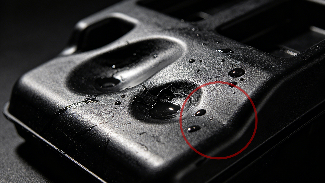
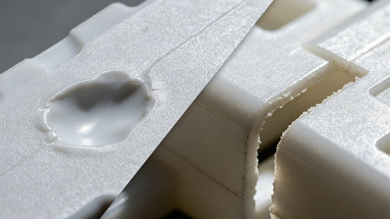
Sink marks in injection molding are surface depressions or indentations that appear on a molded plastic part. They occur when the outer skin of a part cools and solidifies, but the material underneath — typically near thick sections, ribs, or bosses — hasn’t fully cooled yet. As the inner material shrinks during cooling, it pulls the surface inward, creating that telltale dimple. Sink marks are one of the most common injection molding defects and can affect both part aesthetics and structural integrity, particularly on Class A surfaces in consumer electronics and automotive components.
The good news? Sink marks are almost always preventable — if you understand where they come from and how to fight them early in the design and process stages. Let me break it all down.
What Are Sink Marks in Injection Molding?
Before you can fix something, it helps to actually understand what you’re dealing with.
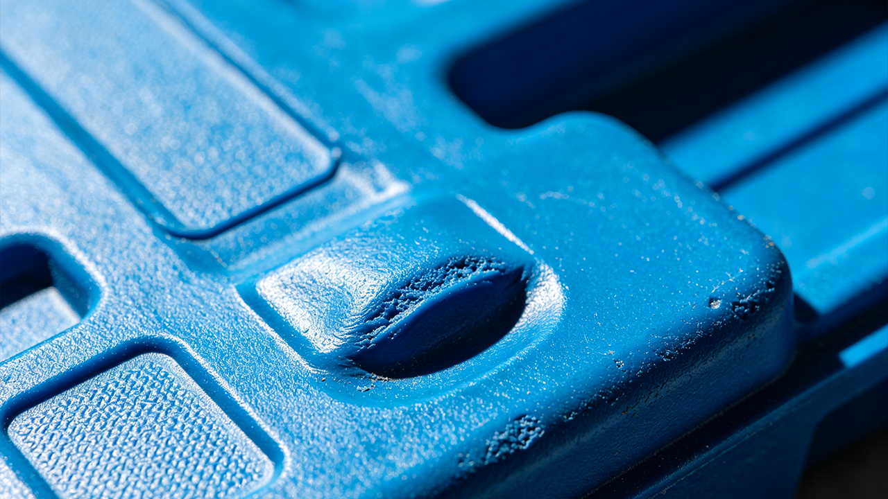
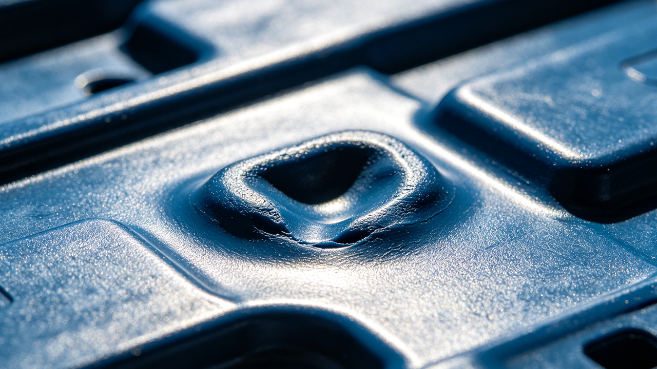
Sink marks are localized surface depressions on injection molded plastic parts. They typically appear on the opposite side of a thick wall section, rib, boss, or internal geometry — anywhere that causes an uneven thickness in the part. The visible “dent” forms because the plastic surface solidifies faster than the interior, and as the hot inner core cools and contracts, it pulls the outer skin slightly inward. In short: the surface collapses toward the shrinkage.
Think of it like a chocolate cake that looks perfect on top but sinks in the middle as it cools. The visual result on plastic parts can range from a barely visible shallow depression to a more obvious dent that ruins an otherwise clean surface.
Where Sink Marks Typically Show Up
They almost always appear in predictable locations:
- Opposite to ribs — the back side of a rib almost always concentrates more material, which means more shrinkage, which means a sink on the visible face.
- Behind bosses — a screw boss adds a bulge of material. If it’s too thick relative to the nominal wall, the face opposite that boss will sink.
- At wall thickness transitions — where a thin wall meets a thick wall suddenly, the thicker zone shrinks more, pulling the nearby surface.
- Near gates — ironically, sometimes the area furthest from the gate has the most sink risk because of insufficient packing pressure.
I’ve seen engineers spend hours tweaking process parameters trying to fix sinks that were actually caused by a rib that was 120% of wall thickness instead of 60%. No amount of parameter adjusting was ever going to fully fix a design issue. That’s the fundamental truth about sink marks — most of them are born in the design file, not on the shop floor.
Why Sink Marks Matter
On a hidden structural part? Maybe you can live with a minor sink. But on a consumer electronics enclosure — the kind of part where customers run their fingers across the surface — a sink mark is a product defect, full stop. It communicates low quality, even when the part is structurally sound.
In automotive interiors, visible sinks can fail appearance approvals. In medical device housings, they can raise questions about dimensional consistency. In any cosmetic application, they erode brand trust. So yes, sink marks matter — a lot.
What Is the Root Cause of Sink Marks?
People often treat sink marks as a “process problem.” Turn up the packing pressure, lower the melt temperature, and done. But that’s only part of the story.
The root cause of sink marks in injection molding is localized volumetric shrinkage — when thick areas of a part cool and contract more than surrounding thin areas, and there isn’t enough packing pressure, material, or cooling capacity to compensate. This stems from three main sources: poor part design (uneven wall thickness, oversized ribs or bosses), incorrect mold design (poor gate placement, inadequate cooling channels), and suboptimal process parameters (insufficient packing pressure or time, incorrect melt or mold temperature).
Let’s look at each one.
Root Cause 1: Part Design Issues
This is the biggest one and the most overlooked.
Uneven wall thickness is the primary design sin. When one section of a part is significantly thicker than the rest, that thick area holds heat longer. It shrinks more. And it pulls nearby surfaces with it.
The classic culprit is the rib-to-wall thickness ratio. Many designers dimension ribs for structural load without thinking about how that thickness translates to a sink risk. A rib that is 80% of nominal wall thickness creates far less shrinkage differential than one that is 100% or more of nominal wall.
Bosses are the same story. A boss for an M3 self-tapping screw can look innocent in CAD but create a significant sink if the outer diameter is too large relative to the surrounding wall.
Design rule of thumb: Keep rib thickness at 50–60% of nominal wall. Keep boss outer wall thickness at 60% of nominal wall. These ratios exist for a reason.
Root Cause 2: Mold Design Issues
Even with a well-designed part, a poorly designed mold can cause sinks.
Gate placement matters enormously. If the gate is too far from thick sections, the plastic cools and the flow front loses pressure before it can pack out those areas properly. The result? Sink marks even with a good part design.
Cooling channel placement is the other big one. If thick areas of the part don’t have adequate cooling near them, the material stays hot too long, increases shrinkage, and creates sinks. Conformal cooling — cooling channels that follow the part geometry — is especially effective for complex parts with thick sections.
Root Cause 3: Process Parameters
Once the design and mold are solid, the process is the final tuning tool.
Insufficient packing pressure is probably the most common process-side cause of sinks. Packing pressure is what compensates for volumetric shrinkage as the part cools. If you don’t push enough material in during the packing/holding phase, you get a gap — and the surface collapses into it.
Too-short packing time has the same effect. If the gate freezes off before the part is fully packed, no amount of high pressure helps — the material can’t get in anymore.
Melt temperature and mold temperature both play a role too. A melt that’s too hot stays fluid longer, increasing total shrinkage. A mold that’s too warm doesn’t create a stiff enough skin to resist the pull of inner shrinkage.
How to Reduce Sink Marks in Injection Molding?
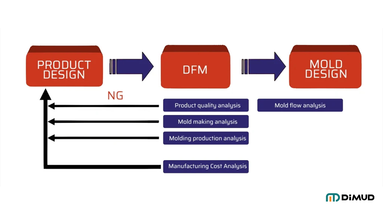
Preventing sink marks starts well before the machine is even running. The most effective time to eliminate them is during the design phase—specifically through DFM (Design for Manufacturability) analysis.
To reduce sink marks in injection molding, focus on three stages: design (maintain uniform wall thickness; follow the 50–60% rib-to-wall ratio rule; core out thick sections; avoid abrupt wall transitions), mold design (optimize gate placement for thick sections; add proper cooling near mass concentrations), and process (increase packing pressure and holding time; lower melt temperature; ensure gate hasn’t frozen prematurely). Catching these issues early in DFM analysis is far more cost-effective than correcting them after tooling.
Design-Stage Strategies to Prevent Sink Marks
1. Maintain uniform wall thickness wherever possible. This is the single most effective rule. A nominal wall that doesn’t vary wildly in thickness means uniform cooling, uniform shrinkage, and no differential pulling.
When you must change wall thickness—say, for structural reasons or to fit a snap-fit or boss—taper the transition. A gradual wall transition (3:1 taper ratio as a minimum) gives the material time to adjust rather than hitting a cliff.
2. Core out thick sections. If you have a thick base or pad, consider coring it out. You keep the structural height while eliminating the mass. Less material = less shrinkage = less sink. This is especially useful for thick base pads, housing feet, and structural ribs on larger parts.
3. Follow rib design guidelines religiously.
- Rib thickness: 50–60% of nominal wall
- Rib height: max 3× nominal wall (taller ribs may need to be slotted)
- Corner radii: add a small radius at the rib base to reduce stress concentrations
- Multiple ribs: use a series of thin ribs rather than one thick rib for strength
4. Boss design rules.
- Boss outer diameter to wall thickness: keep the boss wall at 60% of nominal wall
- Avoid solid bosses — use a cored design
- If the boss needs to be taller, consider gusseting it rather than increasing wall thickness
Mold-Level Strategies
Optimize gate location. Place gates near or directly into thick sections when possible. This ensures packing pressure reaches the areas that need it most before the gate freezes off. For parts with multiple thick sections, consider multiple gates or hot runner systems.
Improve cooling. Thick areas need targeted cooling. Consider:
- Adding cooling channels closer to problem areas
- Using conformal cooling inserts (especially with metal 3D printing)
- Beryllium copper inserts in particularly problematic hot spots
Review venting. Poor venting in thick areas can trap air and restrict material flow during packing, contributing to sinks.
If you’re working with a manufacturer that has real mold engineering depth — not just someone who can cut steel — they’ll do mold flow analysis before cutting a single piece of metal. Mold flow simulation (tools like Moldex3D or Autodesk Moldflow) can predict sink risk and let you adjust before it costs real money. At Dimud, our mold engineering team runs mold flow analysis as standard practice, and we catch exactly these kinds of issues in the design phase before they become a factory problem.
How Do You Adjust Injection Molding Parameters to Eliminate Sink Marks?
Sometimes, despite good design, you still get sinks in production. Or maybe you’re working with a legacy part design you can’t change. This is where process adjustment becomes your best tool.
To eliminate sink marks through process adjustment, increase packing pressure (typically to 60–80% of injection pressure), extend holding/packing time until the gate freezes, reduce melt temperature by 5–10°C increments, lower mold temperature if possible, and increase shot size slightly. Each change should be made one at a time, with short test runs to evaluate the result. Document your baseline before making any changes.
Step-by-Step: Parameter Adjustments for Sink Marks
Increase Packing Pressure
This is usually the first and most impactful adjustment. Packing pressure compensates for volumetric shrinkage by pushing more material into the cavity as the part cools.
Start at your current value and increase in 5–10% increments. Watch for flash at the parting line — that’s your upper limit. If you reach flash before the sink disappears, packing pressure alone isn’t the solution, and you likely have a design or gate issue.
Typical packing pressure is 60–80% of injection pressure, though this varies by material.
Extend Holding Time
Packing time needs to be long enough that the gate freezes before the pressure is removed. If you drop pressure while the gate is still open, the material will flow back out slightly — not enough to matter in fill, but enough to reduce packing in thick areas.
How to check gate freeze time: Run a simple gate seal study. Increase holding time in 0.5-second increments and weigh the parts. When part weight stops increasing, the gate has frozen — that’s your minimum holding time. Add a small safety margin (10–15%).
Reduce Melt Temperature
A lower melt temperature reduces total shrinkage. Materials have a recommended processing range — try processing at the lower end of that range. Be careful: too low, and you risk short shots, poor flow, or weld line issues. Make incremental adjustments.
Adjust Mold Temperature
A cooler mold can help form a stiffer outer skin faster, which resists the pulling force of inner shrinkage. However, this is a balancing act — too cool a mold can cause warpage, residual stress, or poor surface finish.
Optimize the Screw Cushion and Shot Size
If your cushion (the small amount of material left in front of the screw at the end of injection) is too small, you may run out of material to pack during the holding phase. Ensure you have 5–10 mm of cushion consistently.
When Parameters Aren’t Enough
Here’s the honest truth: if you’ve maxed out packing pressure, extended hold time, and adjusted temperatures, and the sink is still there — it’s a design or tooling problem. Process optimization has real limits. No parameter setting can fully compensate for a rib that’s 100% of wall thickness. At that point, you need a mold modification or a design revision.
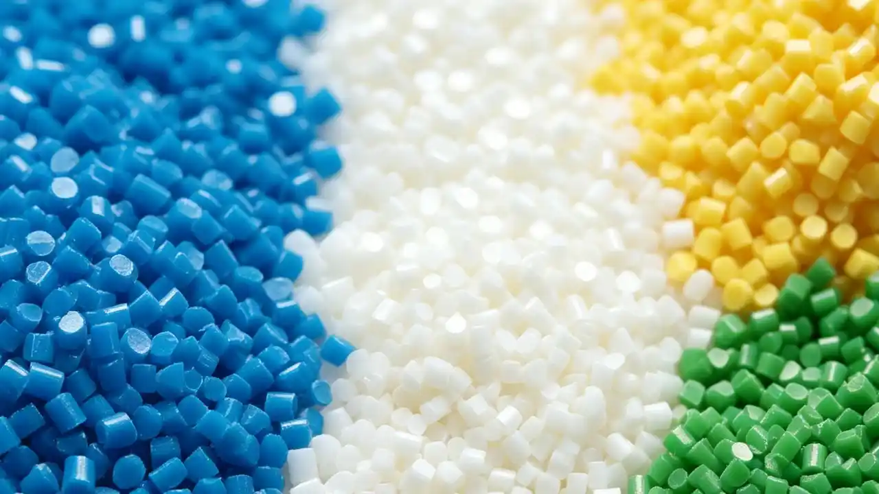
Which Plastic Materials Are Most Prone to Sink Marks, and How to Choose Alternatives?
Not all plastics shrink equally. Material selection has a direct impact on sink mark risk — and it’s a factor that often gets overlooked until parts are already running in production.
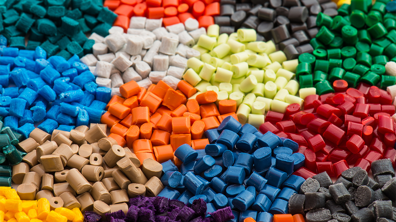
Semi-crystalline plastics such as PP (polypropylene), PA (nylon), POM (acetal), and HDPE are the most prone to sink marks because they have higher and more anisotropic volumetric shrinkage rates (typically 1.5–2.5%). Amorphous plastics like ABS, PC, and PMMA shrink less (0.4–0.8%) and more uniformly, making them significantly less prone to sinking. When sink marks are a critical concern, switching from a semi-crystalline to an amorphous material — or selecting a glass-fiber-reinforced grade — can dramatically reduce the problem.
High-Sink-Risk Materials
Polypropylene (PP): Shrinkage rates of 1.5–2.0%. Extremely common for packaging, automotive, and consumer goods — and extremely prone to sinks in thick sections. Adding glass fiber (PP-GF30) cuts shrinkage significantly.
Nylon (PA6, PA66): Shrinkage of 1.2–2.0%. High shrink, hygroscopic, and particularly problematic in thick-walled structural parts. Glass or mineral filling helps considerably.
POM (Acetal/Delrin): Shrinkage of 2.0–2.5%. One of the highest-shrinkage engineering plastics. Excellent mechanical properties but requires cautious wall thickness design to avoid sinks.
HDPE: Shrinkage of 1.5–3.0%. High shrinkage and a waxy surface make sinks especially visible. Often used in containers where wall uniformity is built into the design.
Low-Sink-Risk Materials
ABS: Shrinkage of 0.4–0.7%. Amorphous, low shrink, excellent surface finish. The go-to for consumer electronics housings partly because it’s forgiving with sinks.
PC (Polycarbonate): Shrinkage of 0.5–0.7%. Low shrinkage, excellent optical clarity, and high-impact resistance. Common in phone housings, automotive lenses, and medical devices.
PC/ABS blends: Combines the best of both. Low shrinkage, good flow, and good surface finish. Very popular for electronics enclosures.
PMMA (Acrylic): Shrinkage of 0.2–0.4%. Among the lowest shrinkage of all common plastics. Great for optical parts but brittle.
Reinforced Grades as an Alternative Strategy
If you need a semi-crystalline material for its mechanical, chemical, or thermal properties, don’t abandon it — reinforce it. Adding 15–30% glass fiber to PP, PA, or POM dramatically reduces shrinkage and makes sink marks much more manageable.
The trade-off is that glass fiber-filled materials require higher injection pressures, are more abrasive to the mold, and may show fiber orientation on the surface. But from a dimensional stability and sink-mark perspective, they’re a significant improvement.
Material selection — and its implications for sink marks — is one of the things our team at Dimud addresses during DFM analysis. Choosing the wrong material for a part with thick sections can set you up for a difficult production life. Getting that right early saves many headaches.
Sink Marks vs. Voids in Injection Molding: What's the Difference and How to Address Each?
This is a question that trips up a surprising number of people — including experienced ones. Sink marks and voids are related defects, but they’re not the same thing, and confusing them leads to the wrong fixes.
Sink marks and voids are both caused by volumetric shrinkage in thick sections of injection molded parts, but they manifest differently. A sink mark is a surface depression visible on the outside of the part — the skin collapses inward. A void is an internal air pocket or vacuum bubble trapped inside the part — the skin is strong enough to resist collapsing, but a gap forms internally. Sink marks are visible; voids are often invisible unless the part is cross-sectioned or scanned. Both require similar root-cause fixes but with different process priorities.
Sink Mark vs. Void: At a Glance
| Feature | Sink Mark | Void |
|---|---|---|
| Location | Surface depression | Internal bubble/cavity |
| Visibility | Visible | Usually invisible externally |
| Detection | Visual inspection | X-ray, CT scan, cross-section |
| Cause | Skin collapses inward | Skin too rigid to collapse; vacuum forms inside |
| Appearance | Dent or dimple on part surface | Internal air pocket |
| Most common in | Thin-skinned parts, semi-crystalline materials | Thick-walled rigid parts, PC, ABS |
| Primary concern | Cosmetics and surface quality | Structural integrity |
Why Do Voids Form Instead of Sink Marks?
When a part has a rigid outer skin — typically because it cooled quickly or it’s made of a stiffer material like PC or ABS—the skin resists the pull of inner shrinkage. Instead of the surface caving in (sink mark), a vacuum pocket forms inside the material. You end up with a part that looks fine on the outside but has a hollow bubble inside.
Voids are particularly dangerous in structural or load-bearing applications. A part with internal voids may pass visual inspection and dimensional checks but fail mechanically under load.
How to Address Sink Marks
- Increase packing pressure and holding time
- Reduce wall thickness or core out thick sections
- Optimize gate placement
- Switch to lower-shrinkage material or use glass-filled grade
How to Address Voids
- Increase packing pressure (same direction as sinks)
- Slow down injection speed slightly — fast injection can trap air
- Improve gate and runner design to allow better packing
- Check for moisture in the material — hygroscopic resins like nylon or PC need proper drying; moisture turns to steam and creates internal bubbles
- Reduce mold temperature to allow a faster-forming outer skin that’s slightly more flexible
The Key Practical Difference
For sinks, the surface is the problem — and you fix it by giving more material to the surface (packing) or by redesigning to reduce the mass differential. For voids, the interior is the problem — and while packing helps, you also need to ensure the outer skin has a bit more flexibility so material can be drawn in rather than creating a vacuum. Drying conditions, injection speed, and back pressure all matter more for voids than for sinks.
If you’re unsure which defect you have, here’s a quick test: press your fingernail gently into the suspected area. If the surface deflects slightly, it’s a sink. If it feels solid but you still suspect an issue, cut the part — or send it for CT scanning.
Should You Use Gas-Assisted Injection Molding to Solve Sink Marks?
Sometimes, no matter what you do with packing pressure and design tweaks, thick sections remain a problem. This is where gas-assisted injection molding becomes a genuinely useful alternative — especially for handles, thick-walled structural parts, and furniture components.
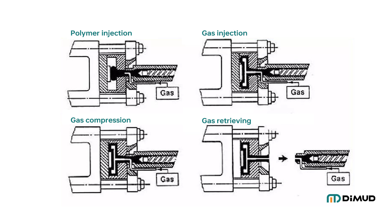
Gas-assisted injection molding eliminates sink marks in thick sections by injecting pressurized nitrogen gas into the part after initial material injection. The gas forms a hollow channel through the thickest part of the geometry, effectively removing the core material mass that causes shrinkage and sinks. This creates a lighter part with a smooth outer surface and eliminates the thick sections that generate sink marks — without requiring major design changes to wall thickness.
How It Works
The process partially fills the cavity with plastic, then injects nitrogen gas through a gas pin. The gas pushes the molten core outward, packing the outer walls against the mold surface while hollowing the interior. The result is a part with a smooth, sink-free surface and a hollow interior in the thick sections.
When Gas-Assist Makes Sense
- Thick-walled parts (handle grips, structural tubes, thick ribs)
- Parts where coring out is structurally not feasible
- Large cosmetic surfaces where any sink is unacceptable
- Parts where reducing weight is also a goal
Gas-assist requires specific tooling design and gas injection equipment, so it’s not a drop-in fix — but for the right part, it’s one of the cleanest solutions to chronic sink mark problems.
How Does Mold Flow Analysis Help Predict and Prevent Sink Marks?
If you’re going to spend money on tooling, spend a little first on simulation.
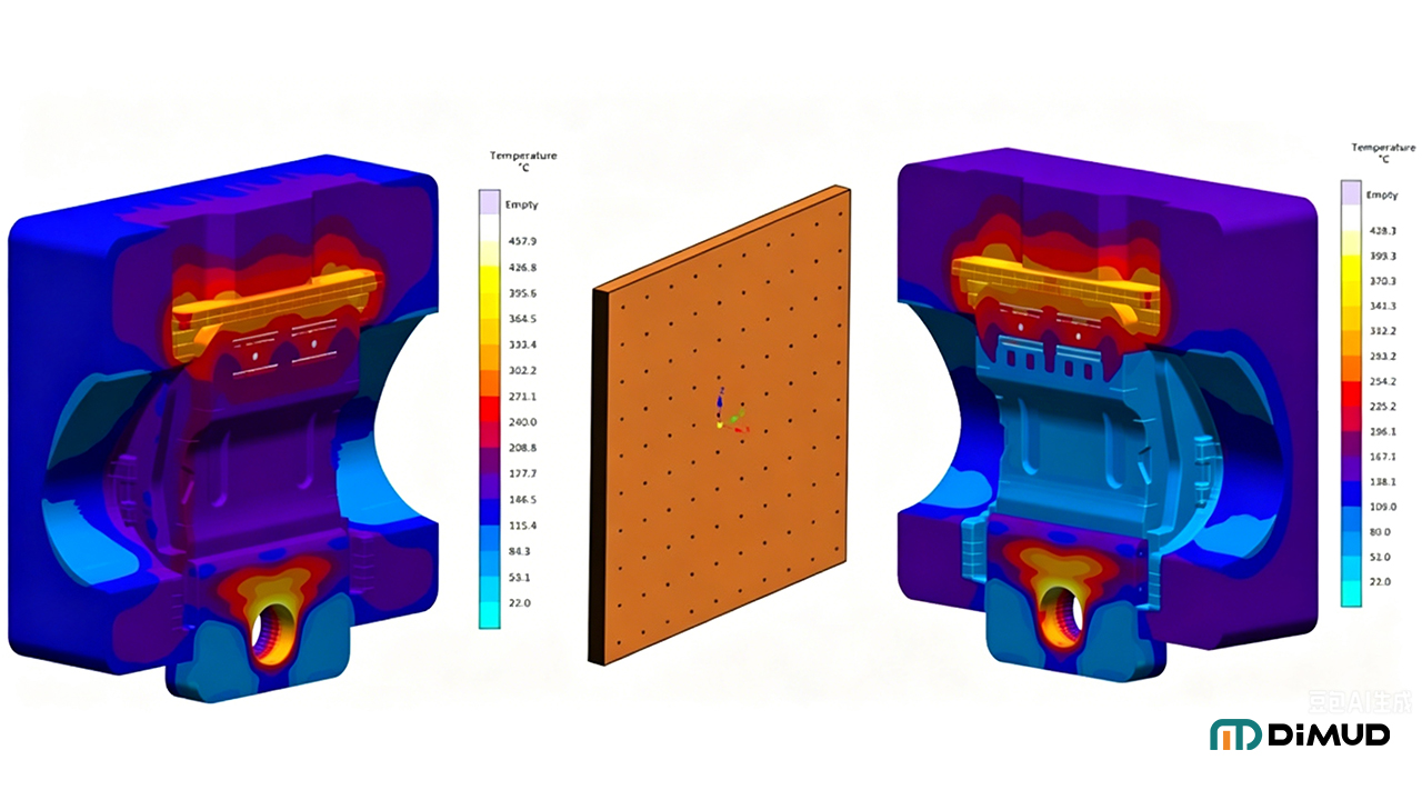
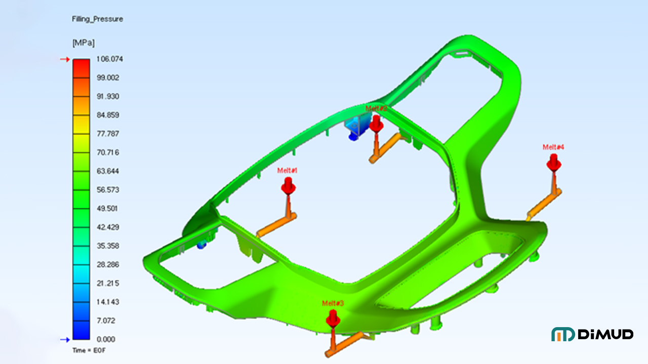
Mold flow analysis (MFA) uses simulation software to model how plastic fills, packs, and cools inside a mold cavity before any physical tooling is made. It can predict sink mark locations, warpage, weld lines, and short shots based on part geometry, material properties, gate placement, and process conditions. Running mold flow simulation before mold fabrication allows engineers to optimize wall thickness, adjust gate positions, and identify shrinkage hot spots — saving significant rework cost after the tool is cut.
What Mold Flow Can Tell You
- Where sinks are likely to occur (shrinkage visualization)
- Whether packing pressure can reach all thick sections
- How gate location affects pressure distribution
- Cooling uniformity and potential hot spots
- Predicted warpage and dimensional deviation
What It Can’t Do
Mold flow is a simulation — it’s based on material databases and idealized conditions. Real-world results can differ. The output is directionally very accurate, but it doesn’t replace good engineering judgment or a well-run first-article inspection process.
Still, in my experience, parts that go through proper mold flow analysis before tooling almost always have fewer first-shot issues than parts that don’t. The simulation cost is a fraction of the cost of modifying a completed tool.
At Dimud, our precision mold manufacturing process integrates mold flow analysis as a standard pre-tooling step. We’ve caught sink risks on hundreds of projects before a single cavity was cut — and our clients consistently tell us that early-stage simulation saved them time and real money.
Conclusion
Sink marks are one of those defects that seem simple on the surface — pun intended — but often trace back to decisions made weeks or months earlier in the design process. The best way to prevent them is to treat wall thickness uniformity, rib-to-wall ratios, and gate placement as non-negotiable design rules from day one.
Process adjustments help. Material selection matters. But if the geometry is wrong, no parameter setting will fully save you. Catch it early — in the design file, in the DFM review, in the mold flow simulation — and your production life gets a lot easier.
If you’re designing a part with thick sections, complex ribs, or cosmetic surface requirements and want to review it for sink mark risk before tooling, our team at Dimud is happy to take a look. Send us your design for a free DFM review and we’ll flag the issues before they cost you a tool modification.