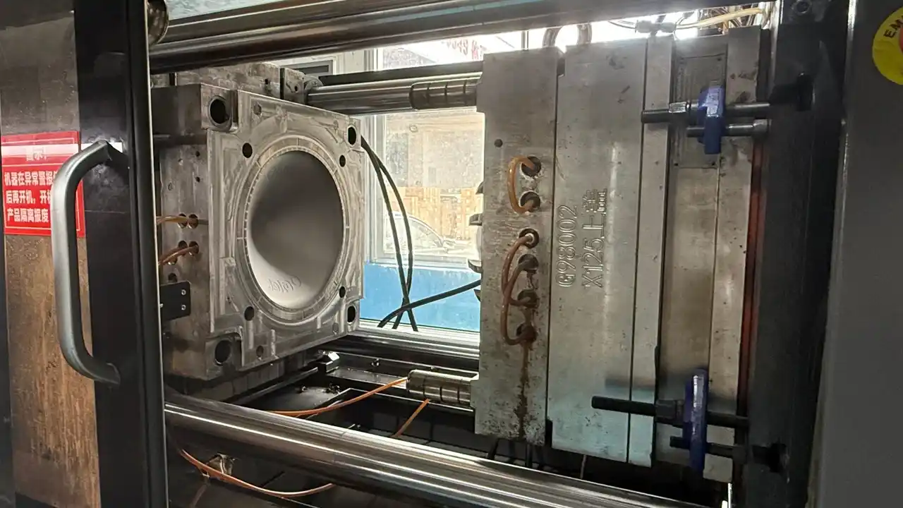
Injection molding is currently the most widely used process for manufacturing plastic parts worldwide. It can produce highly consistent parts in a matter of seconds to tens of seconds and is suitable for nearly all industries, including automotive, medical, consumer electronics, and industrial equipment.
However, injection molding imposes strict design constraints. If product engineers overlook these constraints during the modeling phase and only discover problems after the mold has been built, the cost of mold modification is often more than five times the cost of prevention.
This guide systematically outlines the core elements of injection molding design—from wall thickness, draft angles, parting lines, undercuts, and ejector pins to shrinkage, tolerances, and common defects—to help you make the right decisions during the design phase.
Wall Thickness Design for Injection Molding
Why is wall thickness so important?
Wall thickness is the single most influential parameter in the design of injection-molded parts. It determines:
- The flow path of the plastic within the mold and the completeness of filling
- Cooling time (which directly affects the production cycle)
- Shrinkage and the risk of warpage
- The structural strength of the part
Recommended Wall Thicknesses for Different Materials
| Material | Recommended wall thickness range (mm) | Remark |
|---|---|---|
| ABS | 1.5 – 4.5 | General-purpose engineering plastic with good moldability |
| PP | 0.8 – 3.8 | Shrinkage is relatively high; thin-walled parts require an increase in speed |
| PC | 2.5 – 4.0 | Poor liquidity; should not be too thin |
| PA66 (Nylon) | 0.8 – 3.0 | High hygroscopicity; dimensional changes must be taken into account |
| POM | 1.5 – 3.0 | High shrinkage rate; difficult to control tolerances |
| TPU | 0.5 – 6.0 | Elastomers have a wide range of applications |
| PEEK | 1.0 – 3.0 | High-temperature, high-pressure process; stringent mold requirements |
Three Practical Principles for Wall Thickness Design
Maintain Uniform Wall Thickness
Areas with significant variations in thickness cool at different rates; thicker sections undergo greater shrinkage, which can easily lead to warping and sink marks. When wall thickness must vary, a gradual transition should be used, with the transition length being at least three times the difference in thickness.
Use Ribs Instead of Increasing Wall Thickness
When structural rigidity is required, prioritize adding ribs rather than thickening the main wall. This represents the most critical shift in mindset distinguishing injection molding design from casting design.
Hollow Out Thick, Solid Sections
For areas that are large in volume but do not require solidity, reduce material accumulation by hollowing out the structure (e.g., using recesses or core inserts) to control the risk of sink marks.
Injection Molding Draft Angle Design
What is a draft angle?
A draft angle is a slight taper applied to the side surfaces of a product relative to the direction in which the mold opens. Its purpose is simple: to allow the part to release smoothly when the mold opens, rather than becoming “stuck” or seized by the mold cavity or core.
Without sufficient draft, the part’s surface can be scratched during demolding; in severe cases, this can lead to deformation or even breakage during the ejection process.
Recommended reference values for draft angles
| Surface type | Recommended draft angle |
|---|---|
| Smooth outer surface | ≥ 1° |
| Textured surfaces (such as leather grain or sandblasted finishes) | Base 1° + an additional 1° for every 0.025 mm of texture depth |
| Inner wall of deep cavity (depth > 50 mm) | Add 0.5° for every additional 25 mm |
| Standard MT texture | Typically, 3°–5° is required |
| Side of the reinforcing rib | ≥ 0.5° per side |
A common design error
Many engineers specify a 1° draft angle for cosmetic surfaces but overlook the texture depth. For instance, specifying the MT-11060 texture (with a depth of approximately 0.065 mm) theoretically requires a draft angle of about 3.6° for smooth demolding. If the drawing only specifies 1°, the texture will be damaged during every ejection cycle, leading to rapid texture degradation during mass production.
Recommendation: Once the texture specification is confirmed, collaborate with the mold engineer to verify that the draft angle meets the requirements; do not rely solely on design intent—consider the actual texture depth data.
Planning of Parting Lines and Parting Surfaces for Injection Molding
What is a parting line?
The parting line is the boundary where the moving mold half and the fixed mold half meet, creating a visible seam around the product. The parting surface refers to the complete geometry of this dividing interface.
The location of the parting line directly affects:
- The product’s aesthetic quality
- The complexity of the mold structure
- The feasibility of the mold opening direction
Principles for selecting the parting line location
- Place it at the maximum cross-sectional profile. This simplifies the mold cavity geometries for both the moving and fixed halves, minimizing manufacturing costs.
- Conceal it in non-visible areas. Since a slight seam is inevitable at the parting line, it should be positioned along edges, mating surfaces, or the back of the part where it is hidden from the customer’s view.
- Avoid crossing curved aesthetic surfaces. Parting lines on curved surfaces demand extremely high alignment precision; even slight misalignment creates an unacceptable “step” or ridge on the visible surface.
- Keep the parting surface as simple as possible. Parting along complex curved surfaces significantly increases manufacturing difficulty and precision requirements for mold closure; such designs should only be used when functionally necessary.
Identification and Handling of Undercuts in Injection Molding
What is an undercut?
An undercut refers to a geometric feature on a product that prevents the mold from releasing directly along the mold-opening direction. Examples include side holes, side recesses, internal threads, snap-fits, and side grooves.
Undercuts are not impossible to manufacture; however, each undercut requiring attention necessitates an additional lateral core-pulling mechanism (such as a slider or lifter) within the mold, thereby increasing costs.
Four methods for handling undercuts
Redesign to eliminate the undercut
Modify the product geometry to convert lateral features into features aligned with the mold-opening direction. For example, change a side hole into a through-hole or reorient a snap-fit so it can be released directly. This is the most cost-effective solution.
Slider
Incorporate a lateral core-pulling mechanism into the mold; the slider is retracted sideways before the mold opens normally. This method is suitable for external undercuts. A single slider typically adds 8,000 to 20,000 RMB to the mold cost.
Lifter
Add an angled movement component to the ejection system; the lifter retracts inward while ejecting, thereby clearing internal undercuts. This is suitable for internal snap-fits or internal grooves.
Forced ejection
For elastic materials (such as TPU or soft PP), minor undercuts can be forcibly squeezed past during ejection without requiring additional mechanisms. This is generally applicable when the undercut depth does not exceed 30% of the wall thickness.
Recommended practice: During the product design phase, check every potential undercut against the mold-opening direction. Use the DFM (Design for Manufacturability) report to determine in advance which undercuts can be eliminated and which require mechanical solutions.
Layout of Injection Molding Ejector Pins
Function of Ejector Pins
An ejector pin is a cylindrical rod in an injection mold responsible for pushing the part out of the mold cavity. Once cooling is complete, the ejection system activates, driving the pins forward to release the part from the molding surface.
Ejector pin layout directly affects:
- Whether the part can be released intact and without deformation
- The location of ejector pin marks (and whether they impact aesthetics)
- The balance of stress distribution during ejection
Design Principles for Ejector Pin Layout
- Ensure uniform distribution and balanced force. The number and placement of pins should ensure that ejection force is applied evenly across the part. If the force is concentrated on one side, the part may tilt during release, resulting in surface scratches or indentations (pin marks).
- Prioritize placement in thick-walled areas and rib sections. These areas have the strongest adhesion and highest ejection resistance, making them the priority locations for ejector pins.
- Confirm ejector pin mark locations in advance. Each pin leaves a circular mark (a slight protrusion or depression) on the product surface. During the design phase, confirm with the client which surfaces must remain free of pin marks and adjust pin placement accordingly.
- Avoid excessively small pin diameters. Pins with small diameters are subject to high stress per unit area; they are prone to bending or breaking after prolonged use and often leave noticeable “white marks” (localized whitening) on the product surface. A minimum outer diameter of 2mm is generally recommended.
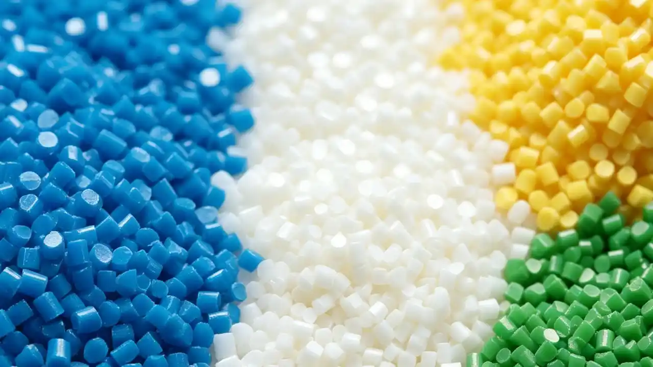
Selection of Injection Molding Materials
Material selection is not an isolated decision; it is directly linked to wall thickness, tolerances, gate design, and mold steel selection.
General-Purpose Thermoplastics
- PP (Polypropylene): Low cost, good chemical resistance, high shrinkage rate (1.0%–2.5%); commonly used for packaging, household goods, and automotive interiors.
- ABS: Balanced overall properties, good moldability; a primary material for consumer electronics housings.
- PE (Polyethylene): Soft, low-temperature resistant; commonly used for flexible tubing and packaging films.
Engineering Plastics
- PA66 (Nylon): Wear-resistant and high-strength; commonly used for structural parts and gears, though dimensional changes due to moisture absorption must be considered.
- POM (Acetal/Polyoxymethylene): High rigidity, good self-lubricating properties; suitable for precision transmission components; high shrinkage rate (1.8%–2.5%).
- PC (Polycarbonate): High impact strength, good transparency; commonly used for LED lighting fixtures and medical device housings.
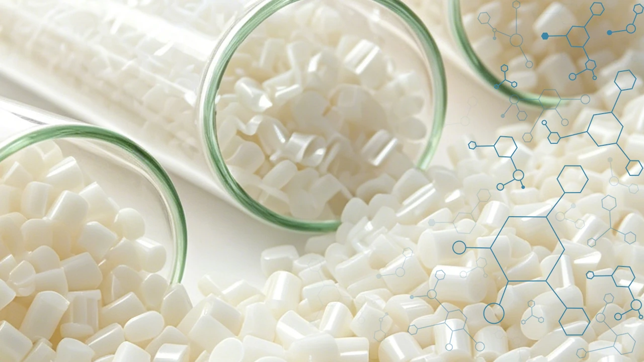
High-Performance Engineering Plastics
- PEEK: High-temperature resistance (long-term service temperature up to 250°C); the preferred choice for medical- and aerospace-grade structural components; high cost.
- PEI (Ultem): Flame-retardant and high-strength; widely used in aerospace and semiconductor applications.
Elastomers
- TPU: Wear-resistant with good elasticity; used for protective cases, seals, and sports shoe midsoles.
- TPE/TPR: Soft to the touch; commonly used for handles, buttons, and the soft-touch sections of two-shot (overmolded) parts.
Key Considerations for Material Selection
When selecting materials, consider the following factors rather than relying solely on mechanical property data sheets:
- Shrinkage Rate: Determines the mold compensation required and the feasibility of dimensional tolerances.
- Flowability (MFI): Affects thin-wall filling and gate design.
- Moisture Absorption: Materials such as PA, PC, and PBT must be dried before molding to prevent defects like silver streaks and bubbles.
- Operating Temperature: The actual service temperature of the part must not exceed the material’s Heat Deflection Temperature (HDT).
Haven’t found the right injection molding material for your project? Check out our injection molding material library.
Control of Injection Molding Shrinkage
What is injection molding shrinkage?
lastics undergo a reduction in volume during the cooling process, a phenomenon known as molding shrinkage. To ensure the final part meets the dimensions specified in the drawing, a shrinkage allowance must be added to the nominal part dimensions when determining the mold cavity size.
Definition of shrinkage rate:
Shrinkage rate = (Mold dimension − Part dimension) / Mold dimension × 100%
Typical shrinkage rates of different materials
| Material | Typical shrinkage rate range |
|---|---|
| ABS | 0.4% – 0.8% |
| PP | 1.0% – 2.5% |
| PC | 0.5% – 0.7% |
| PA66 | 0.6% – 1.0% |
| POM | 1.8% – 2.5% |
| TPU | 0.5% – 2.0% |
| PEEK | 1.2% – 1.6% |
Factors affecting shrinkage rate
Shrinkage is not a fixed value; the following factors can cause deviations between actual shrinkage and theoretical values:
- Wall thickness: Thicker walls cool more slowly, resulting in greater shrinkage. For the same material, the shrinkage rate can differ by more than 0.5% between 2mm and 6mm wall thicknesses.
- Gate location and filling direction: Shrinkage along the filling direction is typically greater than in the perpendicular direction, leading to inconsistent dimensional changes across different axes.
- Mold temperature: Higher mold temperatures result in slower cooling and more complete shrinkage; while this actually yields more stable final dimensions, it slows down the production cycle.
- Injection pressure and holding pressure: Sufficient holding pressure can compensate for some shrinkage, thereby reducing sink marks and dimensional deviations.
- Raw material batches: Shrinkage rates can fluctuate by ±0.2% between different batches of the same plastic grade; precision parts require the use of a specific, locked-in material batch.
Dimensional Tolerance Design for Injection Molding
What level of precision can injection-molded parts achieve?
The dimensional precision of injection molding is lower than that of metal machining, yet it fully meets the requirements of most industrial assembly applications. Higher precision is not necessarily better; overly strict tolerance requirements can significantly increase mold costs and the scrap rate.
Reference for Common Injection Molding Tolerances (ISO Standards)
| Size range (mm) | Standard precision (mm) | Precision (mm) |
|---|---|---|
| 0 – 30 | ±0.20 | ±0.08 |
| 30 – 80 | ±0.30 | ±0.12 |
| 80 – 160 | ±0.45 | ±0.18 |
| 160 – 250 | ±0.60 | ±0.25 |
Achieving high precision requires specific supporting conditions: high-precision mold steel (hardness HRC 48–52), consistent raw material batches, controlled mold and melt temperatures, and—when necessary—post-process dimensional correction.
Which design factors affect the achievement of tolerances?
Shrinkage accuracy: Mold compensation values are calculated based on shrinkage rates; errors in selecting these rates result in systematic dimensional deviations.
Wall thickness uniformity: Uneven wall thickness leads to localized variations in shrinkage, resulting in inconsistent dimensional stability across different areas of the same part.
Part rigidity: Large, flat, thin-walled parts are prone to warping after demolding, leading to poor dimensional repeatability; this requires mitigation through the use of reinforcing ribs or auxiliary fixtures.
Multi-cavity consistency: In multi-cavity molds, dimensional consistency across cavities depends on mold machining precision, which must be explicitly specified in the mold requirements.
DFM Design Self-Checklist
Use this checklist to review your design before submitting it for mold fabrication; doing so can help you identify over 80% of manufacturability issues in advance:
Wall thickness inspection
- Are all wall thicknesses within the recommended range for the selected material?
- Are there any abrupt changes in wall thickness? Are transitions handled using slopes or fillets?
- Is the rib thickness ≤ 60% of the main wall thickness?
- Are there any areas with a wall thickness exceeding 4 mm? Is this necessary?
Draft angle check
- Have draft angles been added to all sidewalls?
- Have additional draft angles been added to textured cosmetic surfaces?
- Is the draft direction correctly defined relative to the parting line?
Parting line inspection
- Has the parting line been confirmed and marked on the drawing?
- Does the parting line avoid Class A cosmetic surfaces?
- Have tolerances been appropriately relaxed for mating dimensions that cross the parting line??
Inverted inspection
- Are there any undercut features?
- Has a solution (elimination, slider, lifter, or forced ejection) been confirmed for each undercut?
- Have the costs for the additional mold mechanisms required to handle the undercuts been included in the cost assessment?
Ejector system inspection
- Have ejector pin locations been planned to avoid visible exterior surfaces?
- Is the ejection surface area sufficient (to prevent stress concentration and “whitening” marks)?
- Are there deep cores or slender features requiring additional ejection support?
Tolerance inspection
- Have tolerances been clearly specified for critical mating surfaces?
- Are the tolerance requirements within the achievable limits for the selected materials and processes?
- Have dimensional tolerances across the parting line been appropriately relaxed?
Common Injection Molding Defects and Their Design Root Causes
Most injection molding defects stem from the design stage. Understanding these root causes allows for prevention during the design phase, rather than relying on process adjustments to rectify issues later.
Sink Mark
Manifestation: Localized depressions on the visible surface of the part, typically occurring opposite ribs or bosses.
Design Root Cause: Excessive material thickness at the corresponding location causes the surface to shrink inward during cooling.
Design Countermeasures: Limit rib thickness to less than 60% of the main wall thickness; hollow out thick, solid sections.
Warpage
Issue: The part warps after demolding and fails to retain its designed shape.
Root causes: Uneven wall thickness leads to varying cooling rates, creating residual stress gradients; or asymmetrical gate placement causes directional differences in mold filling.
Design countermeasures: Standardize wall thickness, employ symmetrical design, and add reinforcing ribs to enhance rigidity.
Weld Line
Manifestation: Fine lines or color variations appear on the part surface, typically around holes or where multiple melt fronts converge.
Design Root Cause: A drop in temperature occurs when melt fronts converge, preventing molecular chains from fully fusing.
Design Countermeasure: Use Moldflow analysis to predict weld line locations and adjust gate positions to direct weld lines toward non-critical areas.
Short Shot
Symptom: Incomplete filling at the end of the part, resulting in short shots.
Design Root Cause: Wall thickness is too thin, flow length is excessive, or gate dimensions are inadequate, leading to excessive flow resistance.
Design Countermeasures: Increase wall thickness in critical flow paths, shorten the flow length, or switch to a material grade with better flow characteristics.
Flash
Manifestation: Excess thin, flake-like flash appears at the parting line.
Design Root Cause: Improper parting surface design resulting in insufficient local clamping force; or the presence of large, thin-walled areas on the parting surface that increase the risk of flash.
Design Countermeasure: Optimize the shape of the parting surface and avoid designing large, thin-walled areas on it.
Voids & Silver Streaks
Symptoms: Internal voids or surface silver streaks.
Design Root Causes: Insufficient material drying (for hygroscopic materials like PA or PC); or localized excessive wall thickness leading to internal shrinkage voids.
Design Countermeasures: Verify material drying specifications; consider coring out thick-walled sections or using gas-assisted molding.
FAQ
There is no universal absolute value for minimum wall thickness; it depends on the material and the part's geometry. Generally speaking:
- For materials with good flowability (such as PP and PA), the minimum wall thickness can be as low as 0.5–0.8 mm.
- For materials with poor flowability (such as PC and PEEK), a minimum thickness of 1.0–1.5 mm is recommended.
- The larger the thin-walled area, the more difficult the filling process becomes, requiring higher injection speeds and mold temperatures.
In actual projects, it is recommended to evaluate the feasibility of minimum wall thickness requirements with a mold engineer during the DFM (Design for Manufacturability) stage, rather than simply modeling based on theoretical limits.
General recommendations are as follows:
- Smooth surfaces: Minimum 1°; 1.5°–2° recommended.
- Textured surfaces: Add 1° for every 0.025 mm of texture depth (e.g., for a depth of 0.075 mm, the angle would be the 3° base angle plus the additional angle for the texture).
- Deep cavities (exceeding 50 mm): Add 0.5° for every additional 25 mm of depth.
A larger draft angle facilitates smoother part release but results in a more pronounced dimensional difference between the top and bottom of the feature. For mating surfaces requiring high dimensional precision, a balance must be struck between the draft angle and dimensional tolerances.
Standard reference ranges (general precision):
- 0 – 30 mm: ±0.20 mm
- 30 – 80 mm: ±0.30 mm
- 80 – 160 mm: ±0.45 mm
Precision injection molding can reduce tolerances by approximately 60%, but it requires high-precision molds and stable process control conditions. Tolerance requirements exceeding the capabilities of metal machining (e.g., tighter than ±0.02 mm) typically require secondary processing to achieve.
Injection molding is suitable for processing almost all thermoplastic materials, which are categorized into three types:
- Commodity plastics: PP, ABS, PE, PS—low cost, highest consumption volume.
- Engineering plastics: PA (nylon), POM, PC, PBT—excellent comprehensive mechanical properties, used for structural components.
- High-performance plastics: PEEK, PEI, PPS—high heat resistance and strength, used in demanding applications such as aerospace and medical sectors.
Elastomers (TPU, TPE) are used for parts requiring a soft touch or elastic functionality, often combined with rigid materials in two-color injection molding.
Priority should be given to eliminating undercuts at the design stage using methods such as:
- Converting side holes into through-holes or blind holes aligned with the mold opening direction
- Reorienting snap-fits to allow for direct demolding
- Relocating internal snap-fits to the exterior or switching to an assembly-based design
For undercuts that cannot be eliminated, mold mechanisms are employed:
- External undercuts: Slider (lateral core pull)
- Internal undercuts: Lifter (retracts during ejection to clear the undercut)
- Small undercuts in soft materials: Forced ejection (undercut depth not exceeding 30% of wall thickness)
Each additional lateral core-pulling mechanism typically increases mold costs by 8,000 to 20,000 RMB; consequently, the return on investment for eliminating undercuts during the design phase is exceptionally high.
Shrinkage is an inherent physical property of thermoplastics, fundamentally caused by the reduction in volume as the plastic cools from a molten state to a solid state. Key factors influencing the degree of shrinkage include:
- Material properties: Crystalline plastics (e.g., PP, POM, PA) exhibit significantly higher shrinkage rates than amorphous plastics (e.g., ABS, PC).
- Wall thickness: Thicker sections cool more slowly, allowing for greater shrinkage and resulting in larger dimensional deviations.
- Holding pressure: Insufficient holding pressure prevents timely compensation for shrinkage, leading to increased sink marks and dimensional deviations.
- Mold temperature: Mold temperature affects the cooling rate, which in turn influences the uniformity of shrinkage.
- Filling direction: Shrinkage rates typically differ between the flow direction and the transverse direction, resulting in anisotropic shrinkage.
At the design stage, shrinkage is controlled by maintaining uniform wall thickness to minimize localized variations in shrinkage. At the processing stage, shrinkage is stabilized by optimizing the holding pressure profile and controlling the mold temperature.
Summarize
Injection molding design is an engineering practice that balances product functional requirements with manufacturing constraints. The eight core elements covered here—wall thickness, draft angles, parting lines, undercuts, ejector pins, materials, shrinkage rates, and tolerances—form a fundamental checklist for design reviews of injection-molded parts.
The cost of making a design decision at the drawing stage is far lower than the cost of modifications during the tooling stage. Adopting a “Design for Manufacturing” mindset is the most effective way to shorten product development cycles and reduce mass production costs.
If you require a DFM analysis for your specific project, please contact the Dimud team; we provide a written analysis report within 24 hours of receiving your 3D data.