PVDF plastic appears almost every time on the material selection lists for chemical fluid piping, semiconductor equipment, medical devices, and new energy battery systems. It is not a general-purpose plastic that competes on price, but rather one that has secured an irreplaceable position in high-end manufacturing thanks to its stable performance even under extreme conditions.
However, precisely because of PVDF’s unique characteristics, many engineers encounter the same confusion when first encountering this material: What problems can it actually solve? What are the technical challenges in injection molding? Under what circumstances should it be selected, and when should it be avoided?
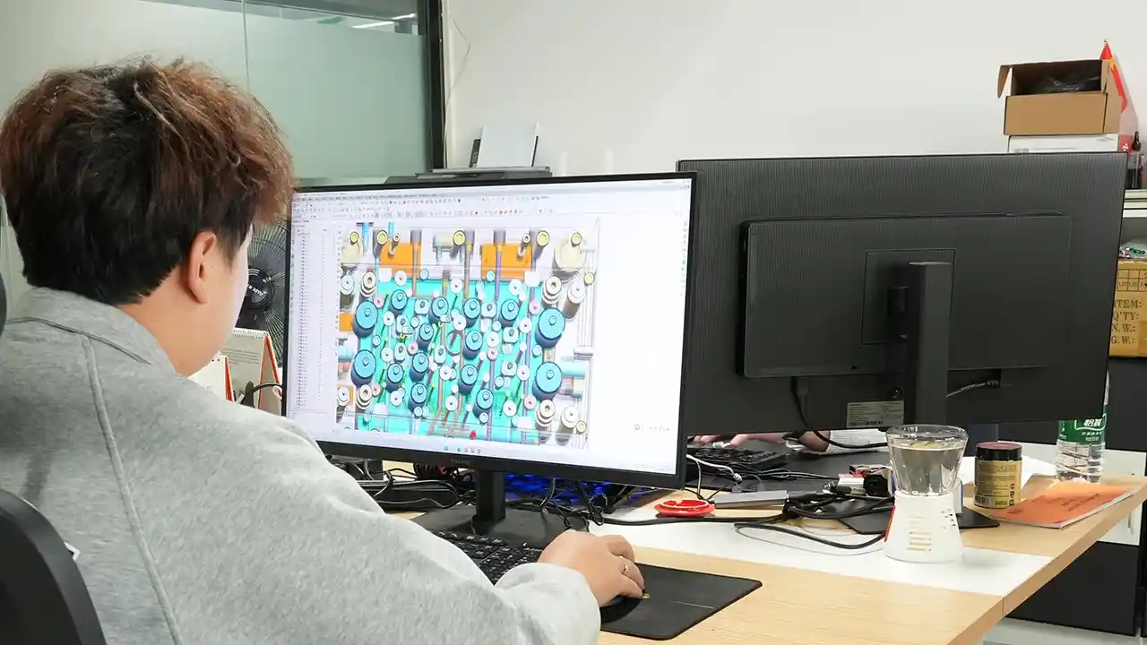
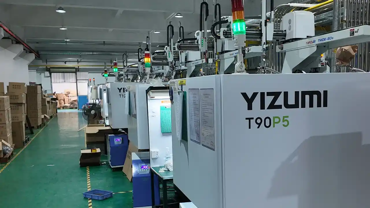
This article will systematically address these questions from the dual perspectives of materials engineers and injection molding manufacturers. The Dimud team possesses years of experience in processing high-performance materials for precision injection molding; the following insights are drawn from our practical engineering judgments accumulated through real-world projects, rather than mere reproduction of reference materials. If you are evaluating material options for your next project, reading this article can save you significant trial-and-error costs.
What is PVDF Plastic?
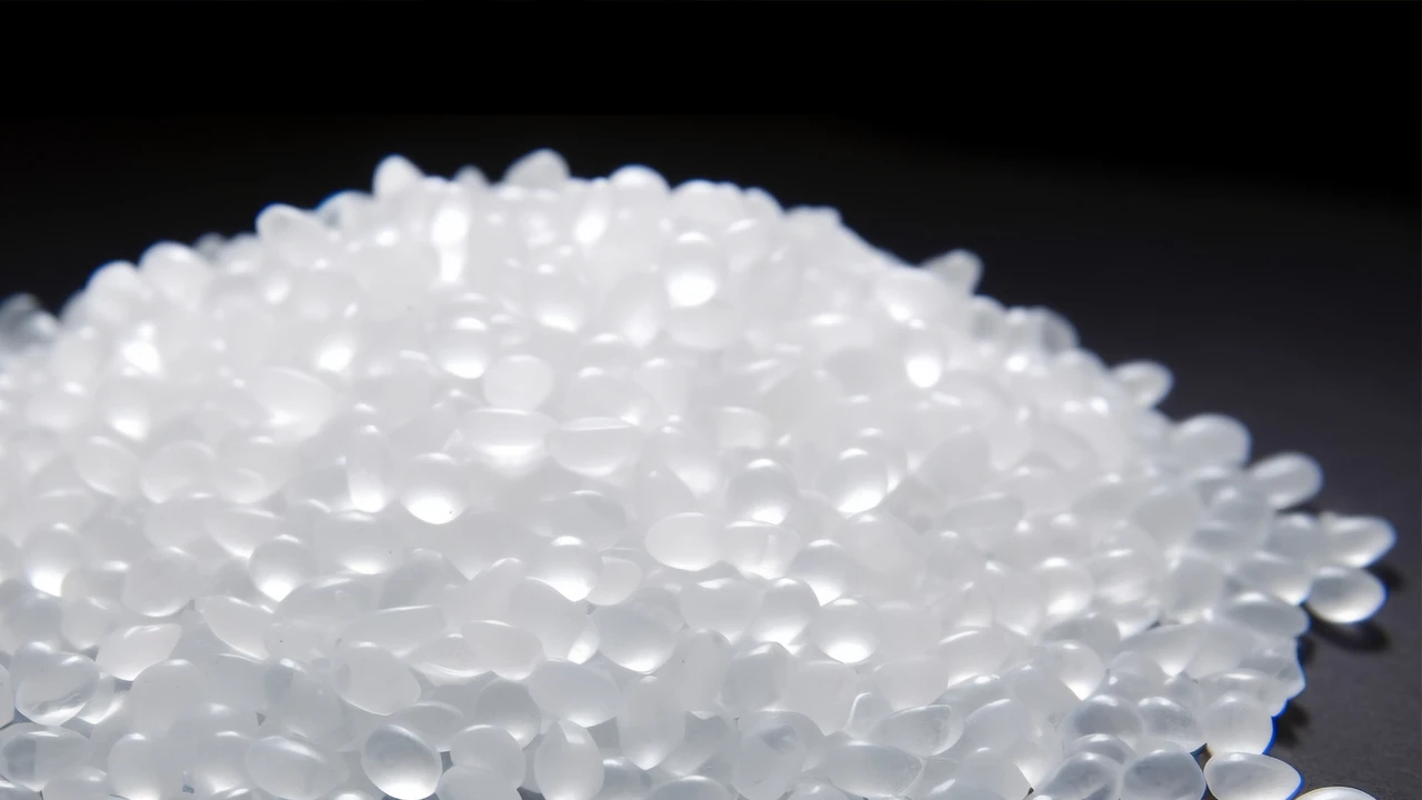
PVDF (Polyvinylidene Fluoride) is a semi-crystalline thermoplastic material and an important member of the fluoroplastic family. Its molecular structure consists of repeating —CH₂—CF₂— units; this regular fluorocarbon backbone confers exceptional stability in extreme chemical and thermal environments.
Compared to PTFE (Polytetrafluoroethylene), PVDF’s most notable engineering value lies in the fact that it retains the core performance advantages of fluoroplastics while also being formable through standard thermoplastic processing methods such as injection molding, extrusion, and blow molding. This makes it one of the best alternatives to PTFE in high-performance applications where processability is a key requirement.
PVDF has a density of approximately 1.75–1.80 g/cm³, with crystallinity typically ranging from 35% to 70%, depending on the grade and processing conditions. The bond energy of the C–F bond in the PVDF molecular chain is as high as approximately 485 kJ/mol, far exceeding that of the C–H bond (approximately 415 kJ/mol), which is the fundamental source of its outstanding chemical inertness. The highly symmetrical distribution of molecular polarity also endows PVDF with unique piezoelectric response capabilities, a characteristic that is extremely rare within the fluoroplastic family.
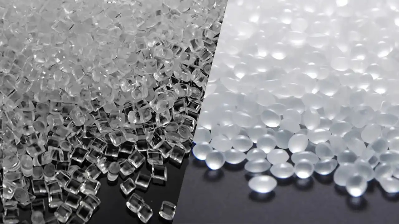
Common commercial grades available on the market include Arkema’s Kynar® series and Solvay’s Solef® series; both brands have established decades-long track records of application in the chemical, medical, and electronics sectors.
Key Properties and Specifications of PVDF Thermoplastic Materials
Understanding the properties of PVDF plastic is essential for making the right material selection decisions. The following provides a systematic overview of its key parameters from multiple perspectives:
Thermal Performance
| Performance Specifications | Typical value |
|---|---|
| Melting point (Tm) | 155–175 °C |
| Continuous operating temperature | -40 °C – +150 °C |
| Heat deflection temperature(HDT,1.82 MPa) | 80–100 °C |
| Coefficient of thermal expansion(CTE) | 120–140 × 10⁻⁶ /K |
| Thermal conductivity | 0.17–0.19 W/(m·K) |
It is worth noting that PVDF can withstand continuous temperatures of up to 150°C, making it a standout candidate among thermoplastic fluoropolymers. Its excellent low-temperature performance (down to -40°C) also makes it suitable for components used in low-temperature energy storage and liquid nitrogen environments.
Mechanical Properties
| Performance Specifications | Typical value |
|---|---|
| Tensile strength | 40–55 MPa |
| Elongation at break | 25–600% |
| Modulus of bending | 1,500–2,500 MPa |
| Hardness (Shore D) | 76–80 |
| Impact Strength (Notched Izod) | 150–200 J/m |
Compared to its counterpart PTFE, PVDF exhibits significantly higher mechanical strength, particularly in terms of modulus and tensile strength, making it better suited for the requirements of engineering-grade semi-structural components. PVDF is also one of the members of the fluoroplastic family with the most outstanding creep resistance, which is crucial for applications such as seals subjected to long-term pressure and pipe fittings.
Chemical Resistance of PVDF
PVDF’s chemical resistance is one of its most distinctive properties. It exhibits excellent resistance to the following media:
- Strong acids: hydrochloric acid, sulfuric acid, nitric acid (non-fuming), phosphoric acid
- Strong oxidizing agents: sodium hypochlorite solution, hydrogen peroxide
- Organic solvents: alkanes, alcohols, esters (some)
- Halogen gases: chlorine, fluorine (low concentrations)
- Aromatic compounds: benzene, toluene
However, PVDF exhibits weaker resistance to the following media, which require careful evaluation:
- Strongly polar non-protonic solvents: dimethyl sulfoxide (DMSO), N-methylpyrrolidone (NMP), dimethylformamide (DMF)
- Nitric fuming acid, sulfuric fuming acid
- Strong bases (high-concentration NaOH, KOH), especially at high temperatures
Electrical Performance
PVDF exhibits piezoelectric and pyroelectric properties, which are extremely rare in thermoplastic polymers. Its specific electrical parameters are as follows:
| Performance Specifications | Typical value |
|---|---|
| Dielectric constant(10 Hz) | 8–12 |
| Dielectric loss(tan δ) | 0.02–0.05 |
| Volume resistivity | 10¹² Ω·cm or higher |
| Dielectric strength | 10–25 kV/mm |
These piezoelectric properties give PVDF unique value in the fields of sensors, energy harvesters, and ultrasonic transducers, representing a competitive advantage that most engineering plastics cannot replicate.
PVDF High Purity Grade
In the semiconductor and biopharmaceutical industries, high-purity PVDF is a critical requirement. High-purity grades (such as Kynar® 740) exhibit extremely low metal ion leaching (<10 ppb) and are compatible with ultrapure water (UPW) and trace chemical environments, meeting compliance requirements such as SEMI F57 and USP Class VI. The production environments and testing requirements for these grades far exceed those of standard industrial-grade materials; therefore, when purchasing, it is essential to explicitly request the corresponding compliance certificates from the supplier.
Advantages and Limitations of PVDF Plastic
Advantages
① Outstanding Chemical Resistance: PVDF exhibits long-term, stable resistance to most acids, oxidizing agents, and halogenated media. In applications involving the transport of corrosive fluids and in chemical processing equipment, it requires no additional anti-corrosion coatings and can come into direct contact with the medium, significantly reducing system maintenance costs.
② Processable via Standard Thermoplastic Methods Unlike PTFE, which requires sintering or machining, PVDF can be directly injection molded, extruded, or blow molded. It is suitable for mass production of complex-geometry PVDF injection-molded parts, offering significant advantages in processing efficiency and cost control.
③ Wide temperature range applicability: From low-temperature energy storage environments at -40°C to hot fluid piping at 150°C, PVDF maintains stable mechanical properties across the entire range, eliminating concerns about low-temperature embrittlement or high-temperature softening failure.
④ Excellent Weather Resistance and UV Resistance: The weathering and aging resistance of PVDF films and coatings is widely recognized. They do not yellow or chalk even after long-term outdoor exposure, and UV radiation has minimal effect on Kynar® resin. There is a substantial track record of its application in architectural curtain wall coatings and outdoor electronic enclosures.
⑤ Unique piezoelectric and pyroelectric properties: This is what distinguishes PVDF from the vast majority of thermoplastic materials, opening up a unique window of opportunity for sensor and energy harvesting applications.
⑥ Excellent Wear Resistance and Anti-Fouling Surface: PVDF has low surface energy and natural non-stick properties. It offers superior wear resistance in applications where it comes into contact with corrosive slurries—such as pump impellers, valve seats, and pipe interiors—while also resisting scaling, effectively extending cleaning intervals.
⑦ Intrinsic Flame Retardancy: PVDF is inherently non-flammable and meets UL 94 V-0 rating (depending on thickness). It satisfies fire safety compliance requirements in most industries without the need for added flame retardants, offering a compliance advantage in the electrical and rail transportation sectors.
⑧ Material Recyclability Unlike some fluoroplastics, PVDF can be reprocessed multiple times using standard thermoplastic equipment. Studies indicate that PVDF exhibits virtually no significant decline in mechanical and physical properties even after up to five reprocessing cycles, providing manufacturers with a viable pathway for scrap material reuse.
Limitations
① High raw material costs: The price of PVDF is approximately 5–15 times that of common engineering plastics (such as ABS and PP), making it less competitive in price-sensitive projects.
② Sensitivity to strong alkalis and polar solvents: Highly polar non-protonic solvents such as NMP and DMSO can cause PVDF to swell or even dissolve. Concentrated alkali solutions at high temperatures can also corrode PVDF. All potential contact media must be clearly identified and evaluated during the material selection phase.
③ Narrow injection molding process window and high equipment requirements: PVDF has strict specifications for processing temperature control, barrel material, and mold temperature. Improper operation can easily lead to degradation and discoloration. Furthermore, the degradation product (hydrofluoric acid) is highly corrosive, posing potential risks to both equipment and operators. It is not suitable for factories without experience in high-performance fluoroplastic injection molding to attempt this process blindly.
④ High injection molding shrinkage makes dimensional control difficult. The linear shrinkage rate of PVDF injection-molded parts is approximately 3%–4% (virgin material), significantly higher than that of amorphous materials such as ABS (0.4%–0.7%) or PC (0.5%–0.7%). This places higher demands on mold dimensional compensation design and process consistency.
⑤ Strength is lower than that of certain high-performance engineering plastics. In applications requiring extremely high tensile strength and rigidity, PEEK or PPS offer superior mechanical performance.
PVDF Grade System and Modification Approaches: How to Choose the Right Grade
When purchasing PVDF, engineers are not dealing with a single product, but rather a vast system of grades. Selecting the wrong grade can lead to processing issues or substandard performance. The following outlines the main classification criteria:
Homopolymers vs. Copolymers
PVDF homopolymers (such as Kynar® 710/720 and Solef® 1006/1008) are the primary choice for standard injection molding and extrusion applications. They feature high crystallinity, a balance of mechanical strength and chemical resistance, and a melting point of approximately 169–174°C.
PVDF copolymers (such as the Kynar Flex® series, containing hexafluoropropylene (HFP) copolymer units) have lower crystallinity, a wider processing temperature window, and produce more flexible molded parts with significantly higher elongation at break. They are suitable for sealing components, hoses, and film applications that require flexibility and low-temperature impact resistance. When selecting copolymers, one must weigh this against their slightly reduced chemical resistance.
Glass-fiber-reinforced grades
As exemplified by Arkema’s Kynar UHM series, adding glass fiber to a PVDF matrix can significantly enhance its structural properties: a typical 20% glass fiber-reinforced PVDF can achieve a tensile strength of up to 120 MPa (approximately 2.5 times that of the unmodified material), a flexural modulus of 6,600 MPa, and a heat deflection temperature of nearly 160°C.
However, it is important to note that if the glass fiber content is too high and the selected glass fiber lacks sufficient compatibility with specific chemical media, it may become a weak link in the material’s overall chemical resistance. In highly corrosive applications, separate chemical compatibility testing is required. Additionally, glass fiber-reinforced grades cause more significant wear on molds and screws; material requirements should be discussed with mold manufacturers in advance.
Conductive/Anti-static Grades
Conductive PVDF grades produced by adding carbon black or carbon fiber can reduce the volume resistivity from insulating-grade levels to 10²–10⁶ Ω·cm, making them suitable for applications in semiconductor manufacturing—such as wafer transfer chutes and chemical distribution lines—where the accumulation of static electricity must be prevented.
High-purity grade
Designed specifically for semiconductor wet processes and biopharmaceutical flow systems, these materials maintain metal ion leaching at extremely low levels and must comply with SEMI F57 or USP Class VI certification. When purchasing, be sure to explicitly request a Certificate of Analysis (CoA) from the supplier.
Selection Recommendations: After identifying PVDF as a candidate material, the next step is to confirm the specific grade with the technical team of the material supplier (e.g., Arkema, Solvay, etc.). Concurrently, conduct a Design for Manufacturing (DFM) review with the injection molding partner to ensure that the melt flow index (MFI) and molding shrinkage of the selected grade align with the mold design parameters.
A Comparative Analysis of PVDF and Other High-Performance Materials
When selecting high-performance materials, PVDF often appears on the same shortlist as PTFE, PEEK, and PPS. Understanding the differences between them is key to avoiding overdesign or selection errors:
| Comparison Criteria | PVDF | PTFE | PEEK | PPS |
|---|---|---|---|---|
| Continuous operating temperature | ≤150°C | ≤260°C | ≤260°C | ≤220°C |
| Tensile strength | 40–55 MPa | 15–35 MPa | 90–100 MPa | 65–85 MPa |
| Chemical resistance | Excellent (except for mildly alkaline solutions) | Strongest (nearly all-around) | Good (use with caution in strong acids) | Good (no known solvents) |
| Injection molding shrinkage | 3–4% | N/A | 1.2–1.4% | 0.5–1.5% |
Key Findings:
- In applications requiring piezoelectric or pyroelectric properties, or where fluid purity is of the utmost importance,
- PVDF is irreplaceable;
For applications requiring continuous operation at temperatures exceeding 150°C or near-universal media resistance, PTFE (not suitable for injection molding) or PEEK should be prioritized; - For cost-sensitive applications with moderate heat resistance requirements, PPS is a viable alternative to
- PVDF, offering better chemical resistance to strong alkalis;
All material selection decisions should be verified on a case-by-case basis in conjunction with specific media and operating conditions; the comparison table is intended solely as a preliminary screening tool.
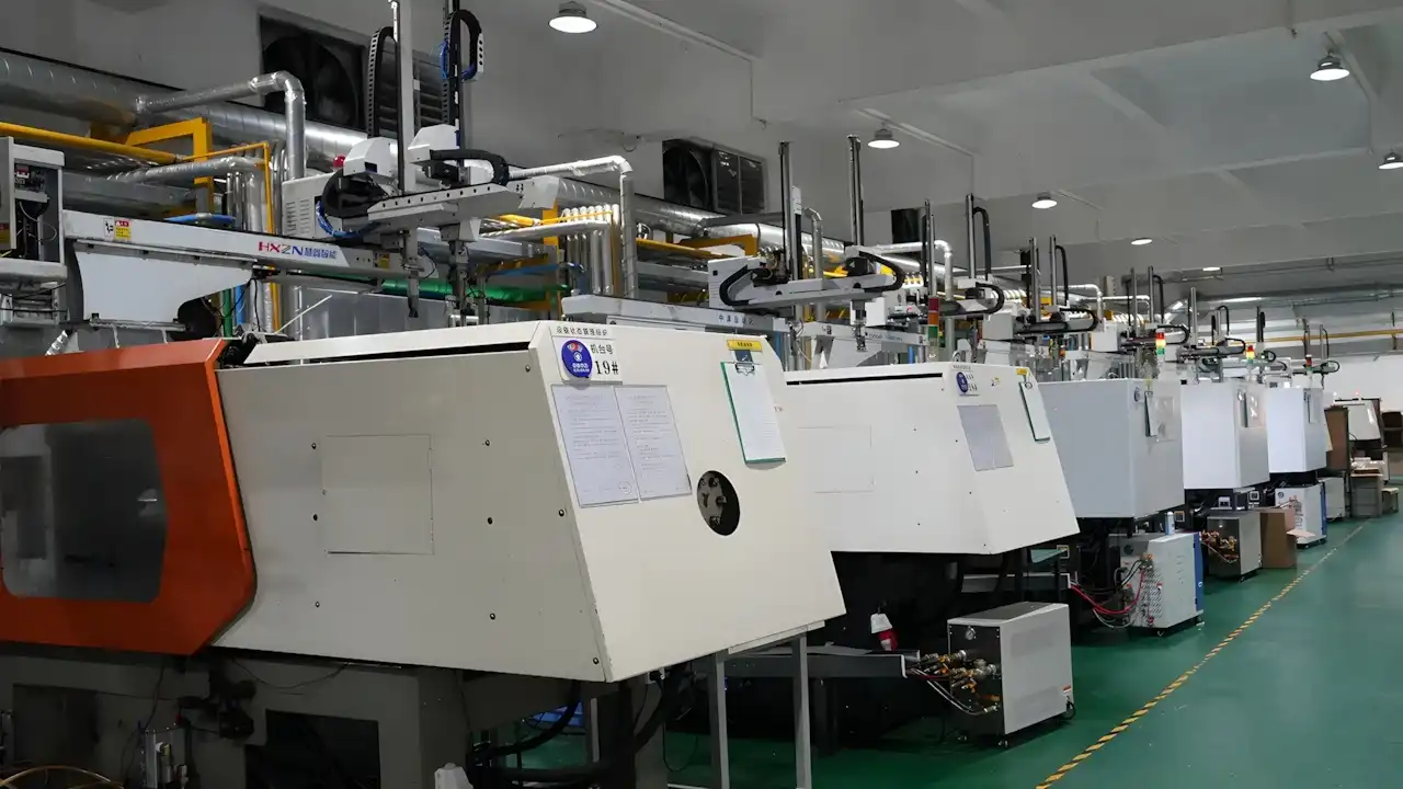
Key Points of the PVDF Injection Molding Process
PVDF injection molding is not a process that can be successfully achieved simply by applying “generic parameters.” The following key points are based on the practical experience accumulated by the Dimud engineering team in the field of high-performance material injection molding:
Material Pre-treatment
PVDF has a low moisture absorption rate (approximately 0.03–0.06%), but it is still recommended to dry the material for 2–4 hours at 80–100°C to eliminate the effects of trace moisture on the part’s surface gloss and internal bubbles. For high-purity grades, clean and dry equipment must be used to avoid cross-contamination.
Barrel Temperature Settings
Typical injection molding temperature ranges:
| Zone | Temperature Range |
|---|---|
| Feed Zone | 190–200°C |
| Compression Zone | 200–220°C |
| Homogenization Zone | 210–230°C |
| Nozzle Temperature | 215–225°C |
Important Note: PVDF begins to thermally degrade and release hydrogen fluoride (HF) at temperatures exceeding 260°C, posing a high risk of severe corrosion to the barrel, screw, and mold, as well as health hazards to operators. Therefore, operating above these temperatures is strictly prohibited; equipment must be equipped with a reliable temperature control system and an over-temperature alarm mechanism.
Equipment Material Requirements: PVDF melt must not come into contact with boron-containing materials (such as boron-containing glass fiber or boronized coatings) or MoS₂ lubricants, as these materials catalyze the spontaneous decomposition of the PVDF melt. Barrels and screws should be made of corrosion-resistant steel (e.g., bimetallic screws, Hastelloy-coated screws). For mold cavities, it is recommended to use corrosion-resistant steel (e.g., S316L or 1.4404) or apply a PVD hard coating to extend service life.
Mold Temperature and Cooling
It is recommended to control the mold temperature between 60–100°C. Higher mold temperatures help increase crystallinity, improve PVDF chemical resistance, and enhance surface quality; lower mold temperatures help reduce cycle times but may induce internal stress. Generally, for parts with stringent chemical resistance requirements (such as chemical process piping and semiconductor components), higher mold temperatures (80–100°C) are recommended to achieve higher crystallinity.
Injection Pressure and Speed
PVDF has moderate melt viscosity, allowing for the use of medium injection pressure (60–130 MPa) and medium injection speed. Excessively fast injection can cause jetting and residual stress, leading to localized reductions in the part’s chemical resistance; conversely, excessively slow injection may result in insufficient weld line strength, which is particularly hazardous in corrosive media.
Shrinkage Compensation
The linear shrinkage rate of PVDF injection-molded parts is approximately 3%–4%. Mold design must allow for sufficient shrinkage allowance based on the target part dimensions. The shrinkage of semi-crystalline materials exhibits anisotropic characteristics (different shrinkage rates along the flow direction and perpendicular to it). For parts requiring high dimensional accuracy, Moldflow analysis should be used to predict shrinkage distribution to avoid extensive rework during the initial mold debugging phase.
Venting and Gate Design
PVDF may release trace amounts of gas at high temperatures; therefore, mold vent channels must be sufficiently deep (0.015–0.025 mm). Gate locations should avoid areas where gas tends to accumulate. Horn gates, point gates, and side gates are all suitable; the optimal solution should be determined during the DFM stage based on the part’s geometry and flow length.
Barrel Cleaning
During material changeovers or machine downtime, the barrel should be thoroughly cleaned using inexpensive resins such as PP or HDPE to prevent PVDF from degrading due to prolonged exposure to high temperatures (which can create degradation points and subsequently cause black spot defects in subsequent batches). If downtime exceeds 15 minutes, the barrel temperature should be reduced to below 180°C while maintaining slow screw rotation to prevent material buildup in dead zones.
Key Considerations for Mold Design of PVDF Injection-Molded Parts
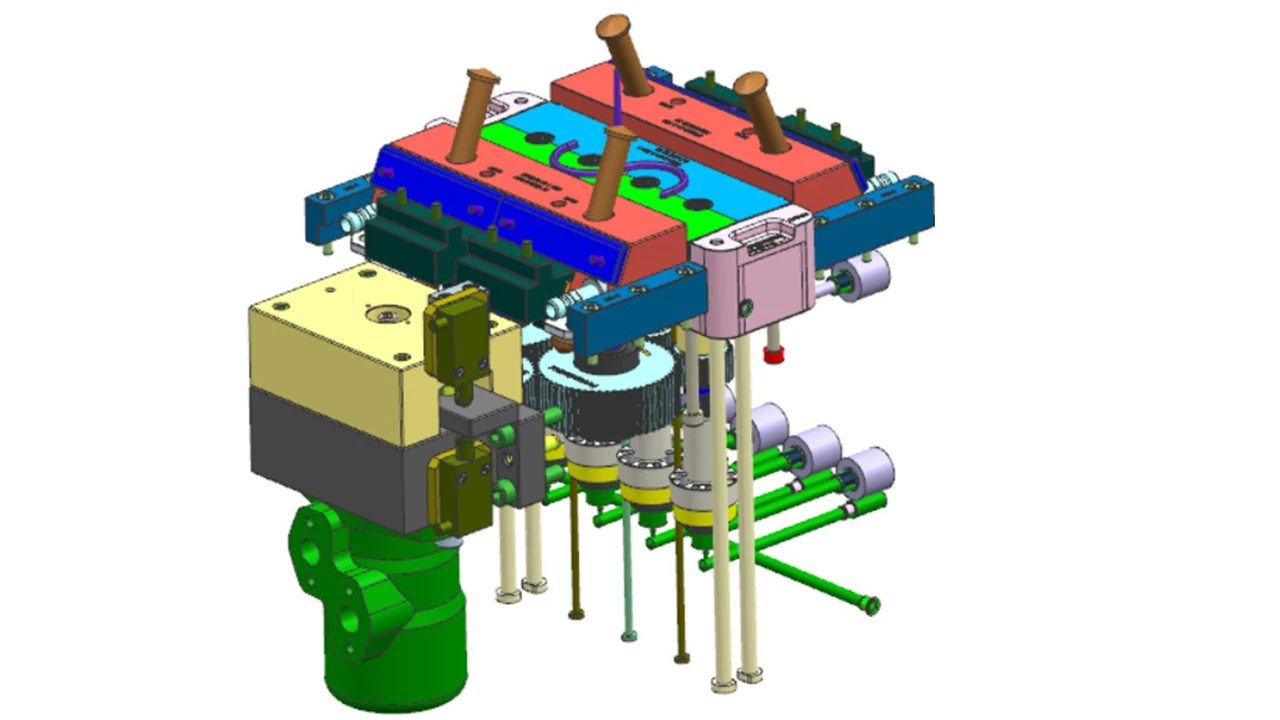
Due to its high shrinkage rate and sensitivity to the processing window, PVDF places far greater demands on mold design than general-purpose plastics. At Dimud, we conduct a detailed DFM (Design for Manufacturability) analysis before undertaking any PVDF injection molding project. The following are key design considerations specific to PVDF:
Wall Thickness Uniformity
PVDF is a semi-crystalline material; uneven wall thickness causes variations in cooling rates across different sections, leading to inconsistent shrinkage and warpage. It is recommended that overall wall thickness variations be controlled within ±15% of the nominal wall thickness. When wall thickness transitions are necessary, use gradual tapers rather than abrupt steps; the transition zone should be at least three times the difference in wall thickness.
For PVDF injection-molded parts, the recommended wall thickness range is 1.5–4.0 mm. If the wall thickness is too thin (<1.0 mm), melt flow resistance increases, making underfill or reduced weld line strength more likely; if the wall thickness is too thick (>4.0 mm), cooling time increases significantly, along with the risk of shrinkage and sink marks.
Draft Angles
PVDF melt exhibits higher adhesion to steel surfaces than many common plastics. If ejection force is not properly controlled, it can result in surface drag marks at best, or part deformation at worst. It is recommended that the draft angle be no less than 1.5° per side (for smooth surfaces); for surfaces with slight texture, the draft angle should be increased to 2.5°–3.0° per side. For deep-wall structures (depth exceeding 50 mm), the demolding scheme should be thoroughly evaluated during the DFM phase, and a tapered sprue or side-gating mechanism should be incorporated if necessary.
Gate Location and Type
The gate should preferably be located at the thickest part of the part wall, following the “thick-to-thin” filling direction principle to minimize stagnant flow and gas entrapment at the end of the filling process. It is recommended that the gate cross-sectional area be no less than 50%–80% of the nominal wall thickness to avoid excessive shear degradation of the PVDF melt (high shear rates accelerate localized degradation of PVDF, leading to discoloration and reduced mechanical properties).
For components in contact with corrosive media, the gate location should avoid forming weld lines on contact surfaces and sealing surfaces, as the crystalline integrity in weld line areas is lower, resulting in weaker chemical resistance.
Cooling System Design
Uniform cooling is the key to controlling warpage in PVDF injection-molded parts. It is recommended to maintain a distance of 15–20 mm between the cooling channels and the cavity surface, with channel diameters typically ranging from 8–12 mm. In multi-cavity molds, the cooling circuits for each cavity should be independent and as symmetrical as possible. For parts with complex geometries, consider using a conformal cooling solution to improve cooling uniformity; this is particularly valuable for high-precision PVDF seals.
Cavity Material and Surface Treatment
Since trace amounts of HF released during PVDF degradation are corrosive to ordinary steel, it is recommended to use corrosion-resistant stainless steel (such as S316L) for the cavity, runner, and gate areas in contact with the PVDF melt. Alternatively, PVD hard, corrosion-resistant coatings such as DLC (diamond-like carbon) or CrN can be applied to the surface of ordinary steel. This also reduces surface roughness to improve demolding performance.
Common Injection Molding Defects and Solutions
In PVDF injection molding, the following types of defects occur frequently; understanding their causes is essential for efficient troubleshooting:
Warping
Causes: PVDF is a semi-crystalline material with a high shrinkage rate (3%–4%), and its shrinkage exhibits anisotropy between the flow direction and the direction perpendicular to the flow. When wall thickness is uneven, cooling is asymmetrical, or holding pressure is insufficient, differences in shrinkage across various areas generate internal stress, causing the part to warp after demolding.
Solutions:
- First, check the temperature difference between the cooling water inlet and outlet on both sides of the mold to ensure it does not exceed 3°C;
- Extend the cooling time to ensure the surface temperature of the part is below the HDT when it is ejected;
- If the problem persists, intervene during the DFM stage to optimize gate location and wall thickness distribution through mold flow analysis.
Discoloration and Black Spots
Causes: PVDF undergoes localized degradation due to prolonged exposure to heat in barrel dead zones or areas of material stagnation. The degradation products are injected into the cavity with the melt, manifesting as yellowish-brown streaks or black spots on the part’s surface.
Solutions:
- Strictly control the maximum barrel temperature to not exceed 240°C;
- Reduce material residence time in the barrel (optimize the ratio of shot weight to barrel capacity);
- Execute a cleaning procedure whenever the machine is idle for more than 10 minutes, using PP or HDPE to flush out residual PVDF from the barrel;
- Inspect the nozzle for any dead corners.
Surface Flow Marks and Jetting
Causes: Excessively high injection speed and a gate cross-sectional area that is too small cause the melt to enter the cavity without spreading near the gate, but instead shoot directly toward the opposite cavity wall, forming serpentine flow marks.
Solutions:
- Reduce the initial injection speed and adopt a staged speed strategy of slow filling of the gate area followed by rapid filling of the cavity;
- Enlarge the gate cross-sectional area to reduce the shear rate;
- Optimize the gate location so that the melt first contacts the cavity sidewall upon entering the cavity rather than shooting directly toward the opposite wall.
Insufficient Weld Line Strength
Causes: Low temperature and insufficient pressure at the point where the two melt streams converge result in incomplete crystallization at the interface, forming a structurally weak weld line, which is particularly hazardous in chemically corrosive environments.
Solutions:
- Increase melt and mold temperatures to improve melt flow at the convergence point;
- Adjust injection speed and holding pressure parameters to ensure sufficient melt pressure in the convergence zone;
- Use mold flow analysis during the DFM stage to predict weld line locations and position them away from areas subject to stress or corrosion exposure.
When to Choose PVDF for Injection Molding?
In the following scenarios, PVDF is the preferred material for manufacturing PVDF plastic parts:
① Long-term exposure to corrosive chemicals: If parts need to be continuously exposed to strong acids, oxidizing agents, or halogen gases, and are expected to have a service life of several years or more, PVDF’s chemical stability significantly reduces maintenance and replacement costs.
② Applications with extremely high requirements for fluid purity: Fittings, connectors, and valve bodies used in semiconductor wafer manufacturing, as well as flow path components in biopharmaceuticals, all require materials that do not leach metal ions or organic contaminants into the fluid. Selecting high-purity PVDF grades is the industry-standard solution.
③ Applications requiring piezoelectric properties: For sensor films, ultrasonic transducer elements, and force-tactile sensing components, PVDF’s piezoelectric response offers an advantage that cannot be matched by other thermoplastic materials.
④ Stable operation over a wide temperature range: In continuous operating conditions ranging from cryogenic temperatures to 150°C, where temperature fluctuations must not cause seal failure or structural deformation, PVDF provides ample thermal performance margin.
⑤ Injection molding for mass production of complex shapes: Unlike PTFE, which can only be machined, PVDF is suitable for injection molding. This makes it ideal for mass-producing PVDF injection-molded parts with complex geometries—such as elbows, valve bodies, fittings, and housings—at a lower overall cost.
⑥ Inherent flame-retardant properties without the addition of flame retardants: PVDF is inherently flame-retardant and contains no halogen-based flame retardants. It is suitable for applications requiring material purity while meeting fire safety regulations, such as electrical enclosures and rail transit components.
⑦ Outdoor weather resistance and UV resistance requirements: For parts requiring long-term outdoor use with demands for color stability and resistance to aging, PVDF outperforms most engineering plastics in this application.
When Should You Avoid Choosing PVDF?
In the following situations, it is recommended to reevaluate material selection to avoid unnecessary costs:
① Contact with strong alkalis or solvents such as NMP, DMSO, or DMF: If high-concentration NaOH or KOH solutions are present in the production environment, or if the process fluid consists of polar non-protonic solvents such as NMP or DMSO, PVDF will exhibit significant swelling or even degradation; PTFE or PFA should be used instead.
② Operating temperatures consistently exceeding 150°C: The maximum continuous operating temperature for PVDF is 150°C. If temperatures exceed this range, PEEK or PPS should be considered. It is important to note that brief transient high temperatures (such as sterilizing steam) differ fundamentally from prolonged continuous high temperatures; evaluation must be based on specific operating conditions.
③ Extreme sensitivity to material costs: If the part’s function can be adequately fulfilled by general-purpose engineering plastics (PP, HDPE, CPVC) under mild operating conditions, the high raw material cost of PVDF will result in an unreasonable BOM expense.
④ Requirement for extremely high structural strength: If the design calls for semi-structural parts with high rigidity and tensile strength (tensile strength requirements exceeding 70 MPa that cannot be achieved through glass fiber reinforcement), PEEK or PPS offer superior mechanical properties.
⑤ Lack of in-house injection molding capabilities for high-performance materials: PVDF has a narrow processing window and imposes higher demands on equipment materials and temperature control precision. If the injection molding supplier lacks experience in processing fluoroplastics, the risk is extremely high; it is recommended to prioritize partners with experience in molding high-performance materials. If you are seeking a manufacturing partner with PVDF injection molding capabilities, please contact the Dimud engineering team for a project evaluation.
⑥ Requirement for transparent or optical-grade materials: PVDF is typically white, translucent to opaque. For optical or display components requiring transparency, PC or PMMA are more suitable choices.
Major Applications of PVDF Plastic in the Industry
PVDF plastic applications span multiple technology-intensive industries. The following is a systematic overview of the primary application scenarios:
Chemical and Fluid Processing
This is the most traditional and mainstream application area for PVDF. PVDF is widely used in the manufacture of pipes, fittings, valves, pump bodies, and tank linings for the transport of strong acids, corrosive gases, and high-purity solvents. Compared to metal piping, PVDF fluid systems require no anti-corrosion coatings and are lighter in weight. In highly corrosive environments such as hydrometallurgy, phosphate chemistry, and the chlor-alkali industry, the service life of PVDF components is typically significantly longer than that of metal alternatives.
Semiconductor and Electronics Manufacturing
In wafer cleaning (wet bench) processes, high-purity PVDF fittings, nozzles, and chemical dispensing valves are standard components, ensuring that ultra-pure chemicals remain free from metal contamination. Additionally, PVDF injection-molded parts are extensively used for the linings of PCB chemical processing tanks and etching equipment. As semiconductor processes continue to shrink (to nodes below 3 nm), material purity requirements are becoming increasingly stringent, driving sustained growth in demand for high-purity PVDF grades.
Medical and Biopharmaceutical
PVDF membranes (particularly the Durapore® series) are widely used in biopharmaceutical filtration, including protein concentration, bacterial retention, and virus filtration. Injection-molded PVDF flow path components (tubing connectors, valve bodies, sampling ports) are used in single-use bioprocessing systems and meet USP Class VI biocompatibility requirements. In the medical device sector, PVDF piezoelectric films are also used in non-invasive diagnostic devices such as ultrasound probes and blood flow sensors.
Dimud possesses specialized process capabilities in the injection molding of medical device components and can provide medical clients with integrated injection molding services ranging from DFM analysis to mass production. We welcome discussions regarding production solutions for compliant components.
New Energy and Battery Systems
PVDF offers dual benefits in lithium-ion batteries: first, as a binder for cathode materials (PVDF binder), it adheres active materials and conductive agents to aluminum current collectors; second, as a separator coating to enhance thermal stability and electrolyte wettability. Injection-molded PVDF components are used in battery module housings, connectors, and liquid cooling piping systems, meeting the stringent requirements for high-temperature resistance and chemical stability in new energy vehicles and energy storage systems. With the advancement of solid-state batteries and large-capacity energy storage systems, the scope of PVDF applications in battery systems will continue to expand.
Oil and Gas
PVDF has established applications in the oil and gas downstream sector, including sour gas treatment, seawater desalination equipment, and chemical piping on offshore platforms. It performs exceptionally well in chloride-ion corrosive environments, serving as an effective alternative to stainless steel. Furthermore, it requires no periodic coating maintenance, resulting in a lower long-term total cost of ownership (TCO).
Piezoelectric Sensors and Energy Harvesting
Polarized PVDF films serve as the core material for piezoelectric transducers, finding applications in hydrophones, ultrasonic transducers, flexible pressure sensors, and haptic interfaces for human-machine interaction. Compared to traditional piezoelectric ceramics (PZT), PVDF piezoelectric films offer advantages such as light weight, high mechanical flexibility, and low acoustic impedance (better matching water and human tissue). They are establishing a unique application ecosystem in the fields of wearable sensors and underwater acoustic detection.
Architecture and Outdoor Infrastructure
PVDF coatings (such as Kynar 500®) are widely used in aluminum curtain walls, color-coated steel roofing, and building facades, offering a weather resistance warranty of over 25 years. This is also the largest non-injection-molding application for PVDF. Injection-molded PVDF parts are also used in outdoor electrical equipment enclosures, photovoltaic system connectors, and piping—applications that require long-term weather resistance.
The Sustainability and Life Cycle Management of PVDF
In a manufacturing environment where ESG pressures are intensifying, procurement teams are increasingly focusing on the environmental performance of materials throughout their entire lifecycle. Here are several key facts regarding the sustainability of PVDF:
Reprocessability
PVDF is a thermoplastic material that, in theory, can be recycled through melt reprocessing. Studies show that PVDF exhibits virtually no significant decline in mechanical and physical properties after up to five reprocessing cycles, in stark contrast to sintered fluoroplastics such as PTFE. In injection molding production, gate sprues and scrap are typically allowed to be mixed with virgin material at a ratio of up to 20% for reuse, reducing material waste costs without compromising performance.
Durability Equals Sustainability
Although the raw material cost of PVDF is relatively high, its extremely long service life in corrosive environments (typically exceeding 20 years in chemical piping systems) results in lower replacement frequency over the entire lifecycle, thereby reducing total material consumption at the system level. This logic aligns closely with the “waste prevention first” principle of the EU Waste Hierarchy and serves as a core argument emphasized by PlasticsEurope in addressing regulatory pressures.
PFAS Regulatory Developments and PVDF Disposal
As mentioned earlier, PVDF falls under the chemical definition of PFAS (containing C-F bonds), but as a high-molecular-weight polymer, its behavior in the environment differs fundamentally from that of low-molecular-weight PFAS (such as PFOA and PFOS)—it is insoluble in water, does not bioaccumulate, and does not migrate into soil or water bodies.
The current mainstream end-of-life disposal method for fluoropolymers is high-temperature incineration (accounting for approximately 83.5% of cases). During incineration, the C-F bond decomposes into inorganic fluorides at high temperatures, which can be treated via exhaust gas scrubbing systems. The specific regulatory trajectory for PVDF under the EU compliance framework is still evolving. Manufacturers supplying the European market are advised to continuously monitor the latest regulatory developments from ECHA and to allow for material substitution assessments during the product design phase.
Frequently Asked Questions
No, they are different, but both belong to the fluoroplastic family. Teflon® is a registered trademark of DuPont for PTFE (polytetrafluoroethylene), while PVDF is polyvinylidene fluoride, which has a different chemical structure and processing properties. The most critical difference is that PTFE cannot be formed via melt injection molding (it can only be sintered or machined), whereas PVDF can be injection molded normally. Additionally, PTFE has a higher maximum operating temperature (approximately 260°C) than PVDF (approximately 150°C), but PVDF possesses mechanical strength and piezoelectric properties that PTFE lacks.
This depends on the specific application requirements; there is no absolute superiority or inferiority between the two. If higher heat resistance (>150°C), a lower coefficient of friction, and the absence of melt processing are required, PTFE is more suitable; if injection molding for mass production, higher mechanical strength, piezoelectric properties, or ultra-high-purity fluid-contacting components are needed, PVDF offers greater advantages. In short: PTFE has a higher performance ceiling, while PVDF offers better processability and overall engineering performance.
Yes, chemically speaking, PVDF falls under the category of PFAS (Per- and Polyfluoroalkyl Substances) because its molecular chain contains C-F bonds. However, PVDF is a high-molecular-weight polymer with stable chemical properties. Unlike short-chain PFAS (such as PFOA and PFOS), it does not accumulate in the environment or exhibit biological toxicity, and its regulatory treatment differs significantly from that of low-molecular-weight PFAS. Currently, major global regulatory bodies generally take a more lenient stance toward PVDF, but relevant regulations are still evolving. It is recommended to monitor the latest regulatory developments in practical compliance efforts.
As of the date of this update, PVDF itself has not yet been comprehensively banned in Europe. EU regulations restricting PFAS (such as the proposed amendment to Annex XVII of REACH) are currently under discussion. While parts of the proposal involve a broad definition of PFAS that could bring PVDF under regulatory scrutiny, it is generally recommended that polymeric PFAS (including PVDF) be exempted or granted a longer transition period. Major European fluoropolymer manufacturers (Arkema, Solvay/Syensqo, AGC, Daikin, etc.) have successfully met their first emission reduction targets by the end of 2024 and are actively collaborating with ECHA to promote differentiated regulation. Manufacturers supplying products to the European market are advised to closely monitor ECHA’s latest announcements and allow for compliance review during the product design phase.
Collaborating with Dimud on a PVDF injection molding project
Dimud is an integrated manufacturer specializing in the development and mass production of high-precision injection molds. With in-house mold, injection molding, and electronics assembly facilities, and holding IATF 16949 certification, we provide end-to-end services—from DFM analysis to delivery—for clients in the automotive, medical, semiconductor, and new energy storage sectors.
In the field of high-performance material injection molding, we have accumulated extensive process expertise and can support precision injection molding requirements for high-end engineering plastics such as PVDF, PEEK, PPS, and LCP, including:
Preliminary DFM manufacturability analysis and gate design optimization
Mold material selection (corrosion-resistant steel solutions)
Moldflow analysis for shrinkage and warpage prediction
Process parameter development and first article inspection (FAI)
Complete handover from small-batch pilot production to mass production
If you are planning a PVDF injection molding project or need to evaluate material substitutions for existing designs, please contact us or visit the Dimud Injection Molding Materials Guide to learn more about the full range of processable materials.