Polyphenylene sulfide occupies the performance tier between standard engineering thermoplastics and ultra-high-performance polymers like PEEK — delivering continuous service temperatures to 220 °C, resistance to virtually every solvent below 200 °C, inherent UL 94 V-0 flame resistance without additives, and precision moldability to tolerances that metal parts require secondary machining to achieve. At 40–60% of PEEK’s material cost, PPS plastic is the engineering material that makes high-temperature precision programs commercially viable.
This guide provides everything engineers need to understand what PPS plastic is, what its key properties and benefits are, how PPS processing and PPS injection molding work in practice, what PPS applications exist across automotive, semiconductor, medical, and robotics industries, and how PPS chemical compatibility determines which service environments the material can and cannot survive. It draws on Dimud’s hands-on experience processing PPS across hundreds of precision programs for customers in Europe, North America, and the Middle East.
What Is PPS Plastic?
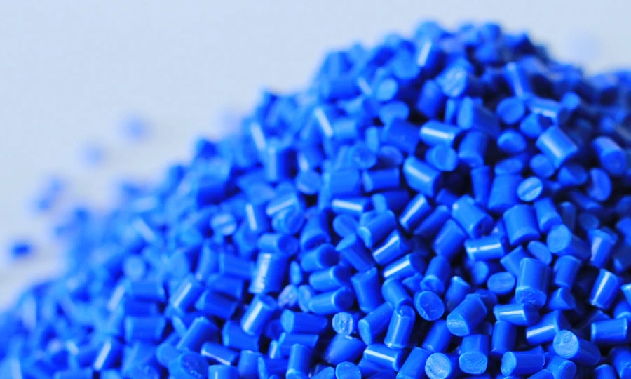
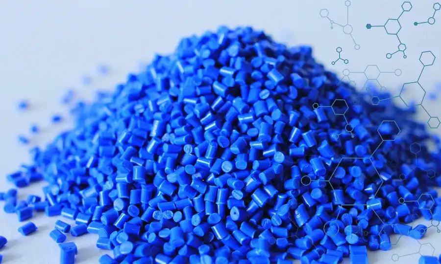
PPS plastic — polyphenylene sulfide — is a semi-crystalline high-performance thermoplastic built from an alternating sequence of para-phenylene rings and sulfide (-S-) linkages in its polymer backbone. This structural simplicity is deceptive: the combination of aromatic benzene rings (providing rigidity and thermal stability) with sulfide bridges (providing flexibility and enabling semi-crystalline chain packing) creates a polymer whose performance profile is surprisingly difficult to match at its price point.
The repeating unit of PPS is one of the smallest in polymer chemistry — a single phenylene ring connected by one sulfide bond — producing a highly regular, symmetrical chain that packs efficiently into crystalline domains during controlled cooling. This semi-crystalline structure is directly responsible for three of PPS’s most commercially important properties:
- Chemical resistance: Crystalline domains act as physical barriers to solvent penetration. PPS does not dissolve in any known solvent below 200 °C — a property unmatched by any other standard injection-molding thermoplastic at comparable cost.
- Thermal stability: The C-S bonds in PPS are strong (~272 kJ/mol) and the aromatic ring provides thermal stability to the backbone, enabling continuous service at 200–220 °C without structural degradation.
- Inherent flame resistance: During combustion, PPS char-forms rather than sustaining a flame — achieving UL 94 V-0 at wall thicknesses as thin as 0.8 mm without any flame-retardant additives or halogen content.
Historical context: PPS was first commercialized by Phillips Petroleum (now Solvay) in 1973 under the Ryton® brand, making it one of the oldest commercial high-performance thermoplastics. This long market history means PPS’s processing parameters, failure modes, and application boundaries are exceptionally well-characterized — a practical advantage for engineers qualifying the material in regulated industries.
At Dimud, PPS plastic programs span automotive electrical connector bodies, semiconductor process equipment components, industrial pump housings, and medical sterilization equipment parts — applications where PPS’s thermal-chemical-electrical performance triad is the commercial justification for its cost premium over PA or PBT alternatives.
PPS Benefits: Why Engineers Specify Polyphenylene Sulfide
Understanding the core PPS benefits helps engineers evaluate where the material earns its specification and where a lower-cost alternative is appropriate. The primary PPS benefits are:
Continuous high-temperature service (220 °C): PPS plastic maintains structural integrity at temperatures that cause PA66 (180 °C max), PBT (155 °C max), and ABS (100 °C max) to soften and creep. Under-hood automotive components, industrial process equipment, and semiconductor manufacturing environments routinely impose this temperature range, and PPS’s crystalline structure maintains dimensional stability throughout.
Inherent UL 94 V-0 flame resistance: Unlike most thermoplastics that require halogenated or phosphorus flame-retardant additives to achieve V-0 rating, PPS achieves V-0 at 0.8 mm wall thickness in its natural form. This simplifies regulatory compliance, eliminates FR additive compatibility concerns, and ensures flame performance is maintained regardless of color or grade variation.
Exceptional chemical resistance: PPS chemical compatibility encompasses virtually all organic solvents, fuels, lubricants, hydraulic fluids, weak acids, and bases — making it the default specification for fluid-contact components in automotive, chemical processing, and industrial equipment.
Precision moldability: PPS plastic’s low mold shrinkage (0.2–0.8% depending on grade and orientation) enables tight dimensional tolerances in injection-molded connector bodies and precision components that cannot be achieved with higher-shrinkage engineering polymers at equivalent cost.
Electrical insulation stability: PPS maintains its dielectric properties (dielectric constant: 3.5–4.0; dielectric strength: 15–20 kV/mm) across a wide frequency and temperature range, making it the specification standard for high-frequency and high-voltage electrical applications in automotive and industrial electronics.
Halogen-free and low outgassing: PPS plastic’s inherent V-0 rating requires no halogen additives, and its low-outgassing profile (particularly critical in semiconductor process environments) meets the stringent contamination requirements of wafer processing equipment.
These PPS benefits combine to create the performance-cost case that makes polyphenylene sulfide the dominant high-performance thermoplastic by volume in automotive electrical systems globally.
Grade Landscape: Linear, Crosslinked, and Reinforced PPS
Linear PPS vs. Crosslinked PPS
The most important structural distinction in PPS plastic is between linear and branched/crosslinked grades — a difference that is not always clearly communicated in supplier datasheets but has significant consequences for processing and part performance.
Linear PPS: Higher molecular weight, better toughness (notched Izod: 50–80 J/m), better melt flow for thin-wall applications, lower flash tendency, and better weld-line strength. Linear PPS is the dominant commercial grade for injection molding and the specification preference at Dimud for precision component programs.
Crosslinked (cured) PPS: Produced by a high-temperature oxidative curing step during polymerization, creating a partially crosslinked structure. Higher stiffness and HDT than linear PPS at equivalent filler content, but significantly more brittle (notched Izod: 20–40 J/m), more prone to flash generation, and harder to process in multi-cavity thin-wall tools. Crosslinked PPS is used primarily in compression molding and in injection molding programs where maximum stiffness at elevated temperatures is the priority and toughness is secondary.
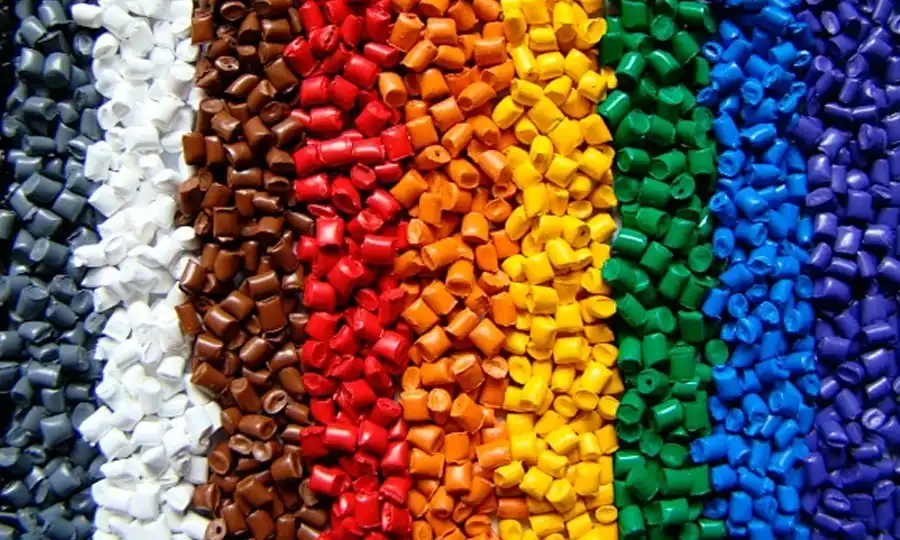
Glass-Fiber Reinforced PPS (GF-PPS)
The dominant commercial grade by volume. Glass fiber addition transforms PPS from a moderately stiff polymer into a high-performance structural material:
| GF Content | Tensile Strength | Flexural Modulus | HDT (1.82 MPa) | Shrinkage (flow) |
|---|---|---|---|---|
| Unfilled | 65–80 MPa | 3,500–4,000 MPa | 115–135 °C | 0.5–1.0 % |
| 20% GF | 120–145 MPa | 8,000–10,000 MPa | 230–245 °C | 0.2–0.4 % |
| 40% GF | 160–190 MPa | 12,000–15,000 MPa | 255–270 °C | 0.1–0.3 % |
| 65% GF (max) | 200–220 MPa | 18,000–21,000 MPa | 265–280 °C | 0.1–0.2 % |
40% GF-PPS is the dominant automotive connector and precision component specification globally — providing the HDT improvement necessary for under-hood service while maintaining the dimensional precision required for connector pin-to-pin spacing tolerances.
Mineral-Filled and Hybrid PPS
Calcium carbonate, wollastonite, and glass bead filled grades provide isotropic shrinkage (reducing warpage in flat components), improved surface finish, and reduced cost versus glass fiber grades:
- Glass fiber + mineral hybrid (30% GF + 20% mineral): Best balance of dimensional isotropy and structural performance for connector housing programs
- Glass bead filled (40% GB): Maximum isotropy; specified for flat housing covers and panel components where minimal warpage is mandatory
Carbon Fiber Reinforced PPS (CF-PPS)
10–30% carbon fiber delivers the highest stiffness-to-weight ratio in the PPS family, approaching CF-PEEK performance at lower material cost. CF-PPS is electrically conductive — disqualifying it from electrical insulation applications but enabling ESD-dissipative use in semiconductor handling equipment.
Specialty Grades
| Grade | Modification | Key Benefit | Application |
|---|---|---|---|
| Impact-modified PPS | Elastomer toughening | Notched Izod > 100 J/m | Structural housings with drop risk |
| Lubricant-grade PPS | PTFE / graphite | Self-lubricating; reduced friction | Pump components, bearing seats |
| Conductive PPS | Carbon black | ESD control | Semiconductor trays, fixtures |
| Food-contact PPS | FDA/EU compliant | Food safety | Food processing equipment |
| Medical-grade PPS | ISO 10993 compatible | Sterilization compatibility | Surgical instrument components |
Key commercial brands: Ryton® (Solvay), Fortron® (Celanese), Torelina® (Toray), Supec® (SABIC).
PPS Properties: Key Physical and Mechanical Data
The following PPS properties table covers unfilled and the two most common reinforced grades — the specifications most frequently required in engineering drawings and supplier qualification documents.
| Property | Unfilled PPS | 40% GF-PPS | 30% GF + 20% Mineral PPS | Test Standard |
|---|---|---|---|---|
| Density | 1.34–1.36 g/cm³ | 1.64–1.68 g/cm³ | 1.70–1.75 g/cm³ | ISO 1183 |
| Tensile Strength | 65–80 MPa | 160–190 MPa | 140–170 MPa | ISO 527 |
| Flexural Modulus | 3,500–4,000 MPa | 12,000–15,000 MPa | 11,000–14,000 MPa | ISO 178 |
| Notched Izod Impact | 25–50 J/m | 50–80 J/m | 40–65 J/m | ISO 180 |
| Elongation at Break | 2–5 % | 1–2 % | 1–2 % | ISO 527 |
| Heat Deflection Temp (1.82 MPa) | 115–135 °C | 255–270 °C | 245–265 °C | ISO 75 |
| Continuous Service Temp | 200–220 °C | 200–220 °C | 200–220 °C | UL 746B |
| Melting Point (Tm) | 278–285 °C | 278–285 °C | 278–285 °C | DSC |
| Glass Transition Temp (Tg) | 85–90 °C | 85–90 °C | 85–90 °C | DSC |
| Mold Shrinkage (flow direction) | 0.5–1.0 % | 0.1–0.3 % | 0.2–0.4 % | ISO 294-4 |
| Mold Shrinkage (transverse) | 0.5–1.0 % | 0.5–1.0 % | 0.3–0.6 % | ISO 294-4 |
| Water Absorption (24h) | 0.02–0.05 % | 0.02–0.05 % | 0.02–0.04 % | ISO 62 |
| Flammability | UL 94 V-0 | UL 94 V-0 | UL 94 V-0 | UL 94 |
| Limiting Oxygen Index | 44–47 % | 47–52 % | 46–50 % | ISO 4589 |
| Dielectric Strength | 15–20 kV/mm | 14–18 kV/mm | 14–18 kV/mm | IEC 60243 |
| Dielectric Constant (1 MHz) | 3.5–4.0 | 4.0–4.5 | 4.0–4.5 | IEC 60250 |
| Chemical Resistance | Exceptional | Exceptional | Exceptional | — |
| Weld-line Strength Retention | 60–70 % | 50–65 % | 55–70 % | ISO 527 |
Dimud Engineering Note — The Weld-Line Warning for PPS
PPS plastic’s weld-line strength retention (50–70% of parent material strength) is one of the lowest among engineering thermoplastics — a consequence of PPS’s semi-crystalline structure and limited molecular diffusion at the weld-line interface. In connector body programs where weld lines form between pin holes, Dimud conducts weld-line strength analysis at DFM stage using Moldflow flow simulation and validates tensile strength at weld-line locations on T1 samples before production release. Gate position design to place weld lines in non-structural zones is a standard DFM objective on all PPS programs.
PPS Chemical Compatibility

PPS chemical compatibility is one of the material’s most commercially important — and most frequently oversimplified — properties. The statement “PPS resists virtually all chemicals” is broadly true but requires engineering-grade precision for application qualification.
PPS Chemical Compatibility — Resistant
PPS plastic demonstrates excellent to outstanding resistance to:
| Chemical Category | Examples | PPS Response |
|---|---|---|
| Aliphatic and aromatic hydrocarbons | Gasoline, diesel, toluene, xylene | No dissolution below 200 °C; minimal swelling |
| Chlorinated solvents | Methylene chloride, TCE | Excellent resistance at ambient temperature |
| Automotive fluids | Engine oil, brake fluid, ATF, power steering fluid | Excellent; automotive qualification standard |
| Dilute acids (< 30%) | Sulfuric acid, hydrochloric acid, nitric acid | Good resistance; concentration and temperature dependent |
| Dilute alkalis | Sodium hydroxide (< 10%), ammonia solutions | Good resistance at ambient temperature |
| Ketones and esters | Acetone, MEK, ethyl acetate | Good resistance; no dissolution or significant swelling |
| Fuel system fluids | E10/E85 ethanol blends, biodiesel | Excellent; automotive OEM qualified |
| Steam | Up to 200 °C | Good to excellent; slight property reduction at extended exposure |
| Hydraulic fluids | HLP, HVLP, water-glycol | Excellent; industrial pump qualification standard |
PPS Chemical Compatibility — Limited or Avoid
| Chemical | Limitation | Engineering Action |
|---|---|---|
| Concentrated oxidizing acids (> 30% H₂SO₄, conc. HNO₃) | Surface oxidation and chain degradation at elevated concentrations | Use PTFE or PVDF in concentrated acid contact |
| Strong oxidizing agents at elevated temperature (ClO₂, H₂O₂ > 35%) | Sulfide group oxidation; surface cracking | Verify with immersion test at service conditions |
| Organic acids at elevated temperature (formic, acetic > 80 °C) | Progressive property degradation | Test at service temperature; consider PTFE |
| Polar aprotic solvents at elevated temperature (NMP, DMSO, DMF > 100 °C) | Swelling and potential dissolution above 200 °C | Avoid for long-term contact at elevated temperatures |
Chemical Compatibility Testing Protocol at Dimud
For applications with non-standard chemical contact, Dimud conducts immersion testing per ISO 175 (plastics — determination of effects of immersion in liquid chemicals) at the service temperature and concentration before program qualification. This is standard practice on all fluid-contact PPS programs in automotive, chemical processing, and medical applications — not an optional add-on.
PPS Processing: Drying, Barrel Temperature, and Crystallinity Control
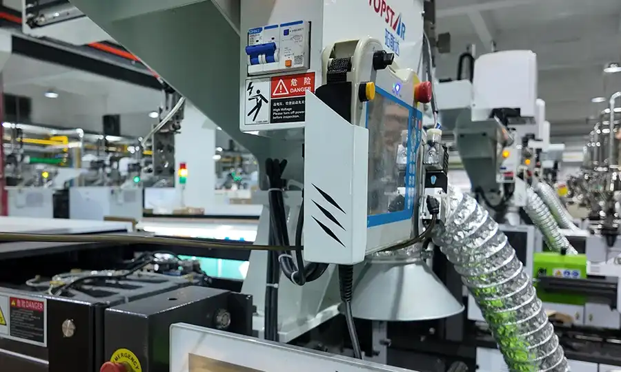
PPS processing shares important characteristics with PET and PEEK: it is semi-crystalline, and the degree of crystallinity achieved during molding directly determines whether the part delivers rated properties or underperforms. Correct PPS processing requires attention to three variables that are less critical in amorphous polymers.
Drying Protocol
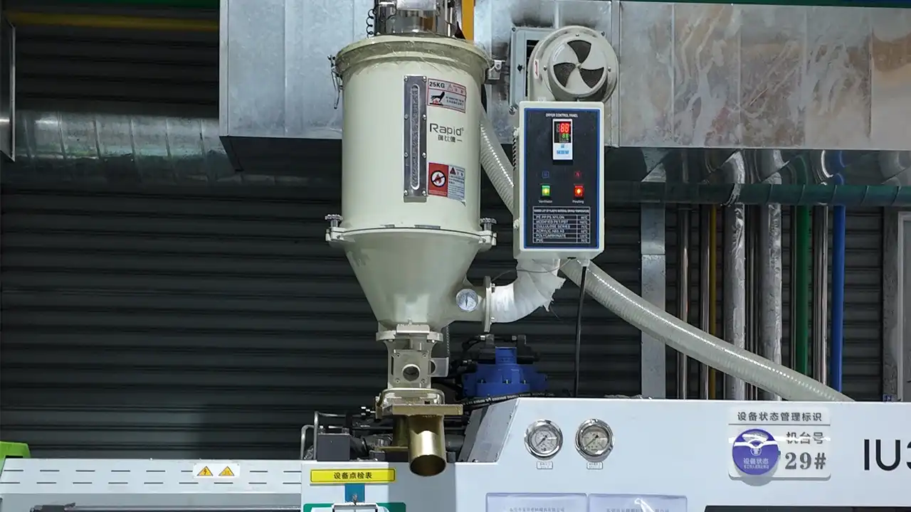
PPS plastic’s water absorption is among the lowest of all engineering thermoplastics (< 0.05% at 24 hours). Despite this, drying before PPS processing is strongly recommended:
| Parameter | Standard PPS | GF/CF-PPS | Medical-Grade PPS | Regrind PPS |
|---|---|---|---|---|
| Dryer type | Dehumidifying hopper | Dehumidifying hopper | Dehumidifying hopper | Dehumidifying hopper |
| Temperature | 150–160 °C | 150–160 °C | 150 °C | 140–150 °C |
| Duration | 2–4 hours | 3–4 hours | 4 hours | 2–3 hours |
| Target moisture | < 0.05 % | < 0.05 % | < 0.02 % | < 0.05 % |
| Max regrind ratio | 20–25 % | 15 % | 0 % (virgin only) | — |
The primary reason for drying PPS is not hydrolysis (PPS is hydrolytically stable) but prevention of drool, cosmetic surface defects, and silver streaks that occur from steam formation at 300–340 °C barrel temperatures when surface moisture is present.
Crystallinity Control in PPS Processing
PPS crystallinity is controlled primarily through mold temperature:
| Mold Temperature | Resulting Crystallinity | Practical Consequence |
|---|---|---|
| 25–50 °C (water cooling) | 10–20% (low) | Lower HDT; increased toughness; transparent/translucent |
| 50–80 °C | 20–30% (moderate) | Partial crystallinity; variable properties |
| 120–140 °C (target for engineering parts) | 30–38% (semi-crystalline) | Full HDT; rated chemical resistance; optimal properties |
| 160–180 °C | 38–45% (high) | Maximum stiffness and HDT; reduced toughness |
The critical engineering consequence: PPS molded at low mold temperature (25–50 °C water cooling) achieves HDT of 115–135 °C (unfilled) — acceptable for some applications but well below the 255–270 °C achievable with 40% GF-PPS at target mold temperature. Engineers who mold PPS without mold temperature control are systematically under-utilizing the material’s rated properties.
For a comprehensive comparison of PPS crystallinity management versus equivalent requirements in PET and PEEK, see the injection molding materials guide.
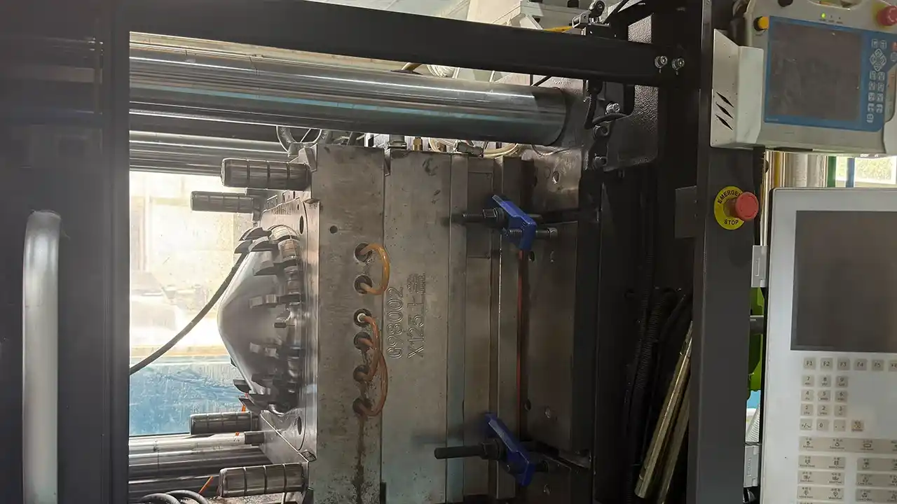
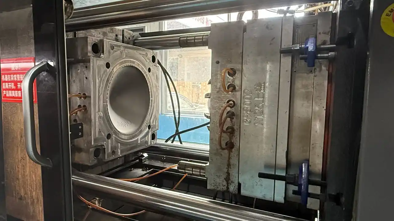
PPS Injection Molding: Process Parameters and Best Practices
PPS injection molding sits between commodity engineering polymers and ultra-high-performance materials in processing difficulty. Barrel temperatures of 300–350 °C require machines capable of sustained high-temperature operation; mold temperatures of 120–160 °C require oil or pressurized water temperature controllers. Engineers transitioning from PA or PBT programs will need equipment upgrades for PPS injection molding.
Barrel and Melt Temperature
| Zone | Unfilled PPS | 40% GF-PPS | CF-PPS | Notes |
|---|---|---|---|---|
| Rear (Feed) | 260–290 °C | 270–300 °C | 275–305 °C | Controlled entry; prevents cold plugs |
| Middle (Compression) | 290–320 °C | 300–330 °C | 305–335 °C | Primary melting zone |
| Front (Metering) | 300–340 °C | 310–345 °C | 315–345 °C | Final melt temperature |
| Nozzle | 295–330 °C | 305–335 °C | 308–335 °C | Open-tip recommended; avoid cold slug |
Degradation ceiling: PPS begins to degrade above 370 °C with discoloration and loss of molecular weight. Barrel temperature must be kept well below this ceiling, and residence time monitored — particularly critical for GF-PPS grades where glass fiber acts as a heat sink that can create localized overheating in the compression zone at high screw speeds. Dimud documents barrel temperature calibration and residence time for every PPS production run.
Mold Temperature for PPS Injection Molding
Target range: 120–160 °C
- 120–140 °C: Standard for automotive connector and precision component programs — optimal balance of crystallinity (30–35%), dimensional stability, and cycle time
- 140–160 °C: Maximum crystallinity development for applications with continuous service above 180 °C or demanding chemical resistance requirements
- Low mold temp (< 80 °C) — avoid for engineering PPS: Produces low-crystallinity PPS with inferior HDT and chemical resistance; only acceptable for non-structural applications
Achieving 120–160 °C mold temperature requires oil-type or pressurized water temperature controllers (not standard water cooling). Dimud uses dedicated oil temperature controllers on all PPS injection molding programs requiring engineering-grade properties.
Injection Speed and Pressure
PPS plastic’s moderate melt viscosity (lower than PEEK, similar to PA66 at equivalent temperature) allows moderate injection speeds:
- Injection pressure: 80–140 MPa for unfilled PPS; 110–160 MPa for 40% GF-PPS
- Hold pressure: 50–70% of injection pressure; extended hold time for dimensional stability
- Back pressure: 5–10 MPa (very low; high back pressure causes fiber breakage in GF grades and excessive shear heating)
- Injection speed: Moderate — fast injection can cause fiber orientation concentrations at the gate and weld-line issues; controlled fill is critical for multi-cavity connector tools
Common PPS Injection Molding Defects and Solutions
| Defect | Root Cause | Corrective Action |
|---|---|---|
| Warpage (flat parts) | Anisotropic GF shrinkage; unbalanced fill | Balanced runner; optimize gate position; hybrid GF+mineral grade |
| Weld lines (weak / visible) | Low melt temp; multi-gate fill convergence | Raise melt temp; reposition gates; raise mold temp |
| Silver streaks / splay | Surface moisture; degradation | Extend drying; reduce barrel temp; check residence time |
| Black specks / discoloration | Thermal degradation in dead zones | Purge thoroughly; check nozzle; rightsize barrel |
| Short shot | High viscosity; insufficient pressure | Raise barrel temp; increase injection pressure; widen gate |
| Flash | Over-packing; worn parting line | Reduce hold pressure; check mold clamping; maintain tool |
| Poor gloss / rough surface | Mold temp too low; fiber exposure | Raise mold temp to 130 °C+; reduce gate shear |
| Brittle fracture at ejection | Sharp corners; insufficient draft | Add minimum 1.0 mm radii; increase draft to 2° |
| Dimensional variation | Crystallinity inconsistency; cooling variation | Stabilize mold temp; verify temperature controller ±2 °C |
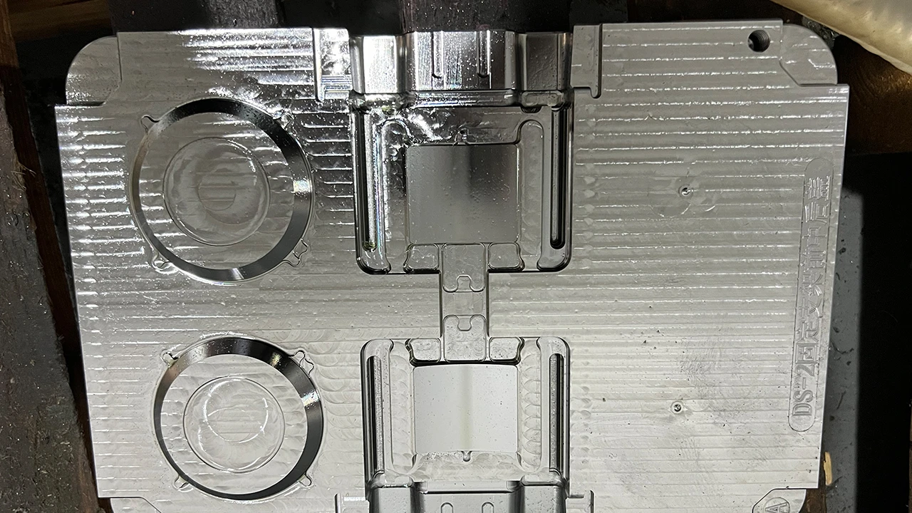
Mold Design Considerations for PPS Molding Programs
PPS molding imposes specific tooling requirements that differ from standard engineering polymer programs, driven by the elevated processing temperatures, crystallinity management requirements, and the abrasive character of glass-fiber and mineral-filled grades.
Steel Selection
| Steel | Application | Shot Life | Notes |
|---|---|---|---|
| H13 hardened (50–54 HRC) | Standard unfilled and 20–30% GF-PPS | 400,000–700,000 | Minimum acceptable for GF grades |
| D2 (62–64 HRC) | 40–65% GF-PPS; high-volume programs | 600,000–1,000,000 | Required for highest GF content |
| H13 + PVD coating (TiAlN) | All GF-PPS gate inserts | 800,000–1,200,000 (gate inserts) | PVD coating standard on all GF-PPS gates |
| S136 stainless | Medical-grade PPS; corrosion-sensitive programs | 400,000–600,000 | Corrosion resistance; good polishability |
P20 is not acceptable for GF-PPS programs. At mold temperatures of 130–160 °C, P20 is operating at 70–80% of its tempering temperature — causing progressive hardness loss, parting line wear, and dimensional drift. Dimud specifies H13 as the minimum steel grade for all PPS injection molding programs involving glass fiber content above 20%.
Heating System
PPS injection molding at 120–160 °C requires active mold heating:
- Oil temperature controllers: Standard on Dimud’s PPS automotive connector programs (operating range: 100–180 °C, ±2 °C stability)
- Insulation plates: Required between mold base and machine platen to prevent heat loss; without insulation, maintaining 140 °C mold temperature consumes excessive energy and produces surface temperature non-uniformity
- Thermal FEA verification: Dimud conducts thermal simulation of PPS mold heating systems before construction to verify ±3 °C uniformity across the cavity surface
Gate Design for PPS Molding
PPS’s moderate-to-good flow characteristics are compatible with most gate types:
- Submarine gates: Standard for multi-cavity PPS connector programs; automatic degating; good dimensional repeatability
- Fan gates: Preferred for flat PPS components (connector covers, housing panels) where anisotropic shrinkage must be minimized
- Hot-runner valve gates: Recommended for high-volume automotive connector programs — eliminates cold runner resin (cost saving at PPS material cost levels), provides precise fill timing to control weld-line position, and enables gate location optimization for cosmetic surfaces. Gate tip material: H13 with PVD coating (mandatory for all GF-PPS hot-runner programs at Dimud)
- Gate land: 0.5–1.0 mm maximum; oversized gate lands increase residence time at the gate and risk thermal degradation
Ejection and Draft
- Draft angles: minimum 1.5°–2° per side (higher than ABS due to PPS’s high stiffness and thermal contraction from 140 °C mold temperature)
- No ejector pins on precision connector mating surfaces; blade or sleeve ejectors on cylindrical PPS parts
- Ejection force calculation at DFM stage for complex PPS geometries with deep rib features
PPS Plastic Sheet and Stock Shape Applications
Beyond injection molding, PPS plastic sheet is an important commercial product for prototype fabrication, low-volume precision components, and applications where the required geometry makes injection molding tooling economically impractical.
What Is PPS Plastic Sheet?
PPS plastic sheet is produced by extrusion or compression molding of PPS resin into flat stock shapes (sheet, rod, tube) that can be precision CNC machined into complex components without tooling investment. Key characteristics:
- Available thicknesses: 1–100 mm (sheet); rod diameters: 10–200 mm
- Grades: unfilled, 30–40% GF, PTFE-filled (wear grade), carbon fiber
- Standard dimensions: 600 × 600 mm or 1,000 × 2,000 mm sheet stock
- Machining: excellent; PPS plastic sheet machines cleanly with standard carbide tooling
When to Specify PPS Plastic Sheet vs. Injection Molding
| Criterion | PPS Plastic Sheet (Machined) | PPS Injection Molding |
|---|---|---|
| Production volume | 1–500 units | > 500 units annually |
| Geometry complexity | Moderate (CNC-machinable) | High (undercuts, multi-wall, snap-fits) |
| Lead time | 2–5 days (from stock) | 25–45 days (tooling + sampling) |
| Dimensional tolerance | ±0.025–0.05 mm (machined) | ±0.05–0.15 mm (molded) |
| Cost per unit | High (machining labor) | Low at volume (tool amortized) |
| Material utilization | 20–60% (machining waste) | > 95% (near net-shape) |
For prototype qualification of PPS programs, Dimud’s standard workflow uses CNC-machined PPS plastic sheet samples for engineering validation before production tool investment — enabling the customer to validate material performance in the application environment before committing to injection molding tooling cost.
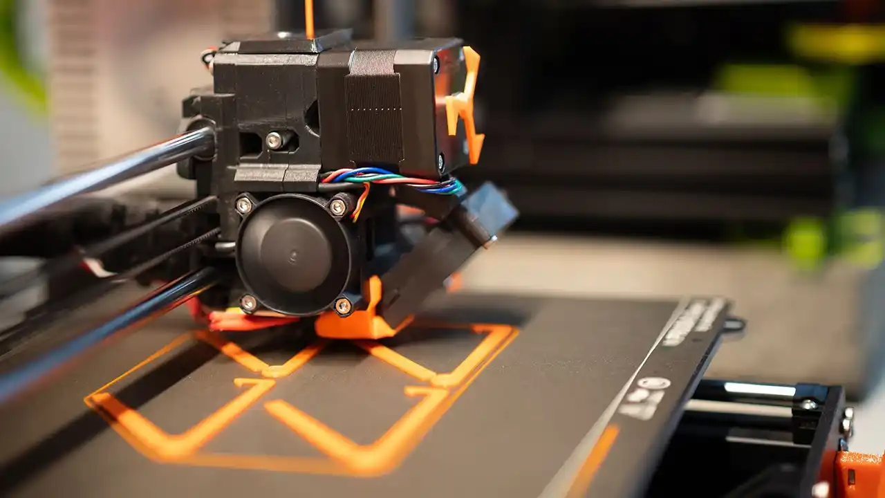
PPS Plastic 3D Printing: Additive Manufacturing Considerations
PPS plastic 3D printing has become commercially available through several additive manufacturing processes, and engineers evaluating PPS for low-volume or prototype programs increasingly ask whether 3D-printed PPS is an alternative to injection-molded or machined stock shapes.
Available PPS Plastic 3D Printing Processes
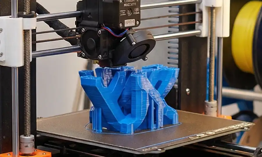
FFF/FDM (Fused Filament Fabrication): PPS filament is commercially available from several suppliers. Processing requires:
- Nozzle temperature: 290–320 °C (requiring an all-metal hotend — standard PTFE-lined hotends cannot survive PPS processing temperatures)
- Bed temperature: 100–130 °C (requires enclosure heating to prevent warpage)
- Enclosure temperature: > 70 °C
- Drying: mandatory at 150 °C / 4 hours before printing
Selective Laser Sintering (SLS): PPS powder is processed in industrial SLS machines (EOS, Farsoon) typically at laser sintering temperatures of 160–180 °C. SLS PPS produces isotropic mechanical properties and is used for complex prototype geometries.
Performance Comparison: PPS Plastic 3D Printing vs. Injection Molding
| Property | 3D Printed PPS (FFF) | 3D Printed PPS (SLS) | Injection-Molded PPS |
|---|---|---|---|
| Tensile Strength | 40–60% of injection-molded | 60–80% of injection-molded | Rated (baseline) |
| Dimensional Accuracy | ±0.2–0.5 mm | ±0.1–0.3 mm | ±0.05–0.15 mm |
| Surface Finish | Rough (layer lines) | Powder texture | Smooth (tool surface) |
| Chemical Resistance | Reduced (anisotropic crystallinity) | Moderate | Full rated resistance |
| Cost at > 500 units | High | High | Low (amortized tooling) |
| Lead time (first parts) | 1–3 days | 3–7 days | 25–45 days |
Dimud’s Recommendation on PPS Plastic 3D Printing
PPS plastic 3D printing is appropriate for: early-stage design validation, fit-and-form checking, one-off prototype fixtures, and applications where injection molding tooling cannot be justified economically. It is not appropriate for: parts requiring rated chemical resistance, full mechanical properties, precision dimensional tolerances (< ±0.1 mm), or surface finish quality.
For any PPS program intended for production use, Dimud recommends injection-molded or CNC-machined PPS from the outset — the property gap between additive and injection-molded PPS is too significant for production qualification to rely on printed samples.
PPS Applications Across Key Industries
Automotive — The Dominant PPS Application Domain
Automotive accounts for approximately 60–70% of global PPS plastic consumption, driven by the simultaneous requirements of high-temperature performance, chemical resistance, dimensional precision, and flame compliance that PPS satisfies better than any competing thermoplastic at its cost point.
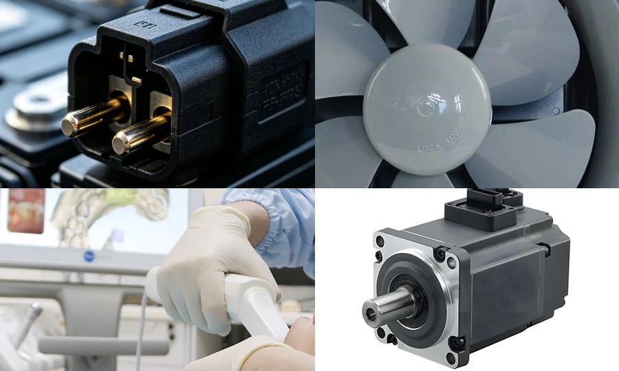
Precision electrical connector bodies (40% GF-PPS): The largest single PPS applications category globally. Automotive electrical connectors — ABS/traction control, powertrain ECU, fuel injection, battery management, EV high-voltage systems — are molded from 40% GF-PPS because the combination of HDT (255–270 °C), chemical resistance to automotive fluids, dimensional stability (low shrinkage 0.1–0.3%), and UL 94 V-0 compliance is uniquely available in this material at production-volume economics.
Dimud produces automotive connector bodies in 40% GF-PPS to IATF 16949-aligned quality standards, with PPAP Level 3 documentation, SPC on critical pin bore dimensions (typically ±0.05 mm tolerance), and dimensional reports as standard deliverables.
EV battery system components (40% GF-PPS / FR-PPS): The transition to electric vehicles has accelerated PPS adoption — EV battery pack connectors, bus bar housings, high-voltage disconnect switches, and cell module insulating components all leverage PPS’s combination of dielectric performance, V-0 flame resistance, and thermal stability at battery operating temperatures (80–120 °C continuous; 150 °C peak thermal event).
Fuel system components (chemical-resistant PPS): Fuel pump housings, filter housings, fuel rail components, and injector surrounds in gasoline and diesel engines. PPS’s resistance to fuels, ethanol blends, and fuel system additives over 15-year vehicle service life is the qualification driver.
Under-hood fluid handling components (GF-PPS / hybrid PPS): Coolant pump impellers, thermostat housings, water outlet flanges, and HVAC compressor components. PPS’s combination of HDT (255–270 °C at 40% GF), glycol coolant resistance, and dimensional stability enables replacement of machined aluminum components at 60–70% mass reduction.
Semiconductor and Electronics
Wafer process equipment components (unfilled / low-outgassing PPS): PPS plastic is widely specified for semiconductor process equipment components including plasma etch chamber parts, chemical vapor deposition fixtures, and wafer handling robot end-effectors. PPS’s combination of chemical resistance to process gases and etch chemistry, thermal stability at process temperatures (150–200 °C), and low outgassing at elevated temperatures enables use in front-end semiconductor fabrication environments where most engineering polymers are disqualified by ionic contamination or outgassing.
SMD connector and socket bodies (40% GF-PPS): Surface-mount electronic connectors requiring reflow solder compatibility at 260 °C peak temperature. PPS is the dominant material for SMD connector housings because its melting point (278–285 °C) provides the safety margin above 260 °C reflow temperature that most engineering thermoplastics cannot achieve.
High-voltage insulation components (unfilled PPS / GF-PPS): Power electronics connectors, relay housings, and transformer bobbins operating above 600V. PPS’s dielectric strength (15–20 kV/mm) and stability across temperature and humidity ranges makes it the specification standard for high-voltage power electronics in industrial and automotive applications.
Dimud supports electronics and semiconductor PPS programs through our integrated electronics manufacturing capabilities.
Industrial and Chemical Processing
Chemical pump housings and impellers (wear-grade PPS): Industrial pumps handling aggressive process chemicals — mineral acids, caustics, solvents — below 200 °C operating temperature. PPS plastic’s chemical resistance profile (Section 5) covers the majority of industrial process chemistries, enabling polymer pump construction that eliminates the corrosion failures and maintenance costs of metal pumps in chemical environments.
Valve bodies and flow control components (PPS): PPS injection molded valve bodies for industrial process control, replacing investment-cast stainless steel components at equivalent chemical resistance with 50% mass reduction and net-shape production economics.
Industrial filter housings and analytical instrument components (GF-PPS): Process filter housings, inline analyzer probe bodies, and sampling system components in petrochemical, pharmaceutical, and water treatment applications.
Medical and Sterilization Equipment
Surgical instrument sterilization system components (PPS): PPS plastic’s compatibility with steam autoclaving (repeated cycles at 134 °C), chemical disinfectants, and gamma sterilization makes it suitable for structural components in sterilization equipment — trays, racks, and instrument holders that must withstand thousands of autoclave cycles without dimensional change or surface degradation.
Dental handpiece and instrument components (medical-grade PPS): PPS’s combination of autoclave compatibility, chemical resistance to dental disinfectants, and dimensional stability under repeated thermal cycling addresses the demanding requirements of dental instrument housing components.
For Dimud’s full medical manufacturing capabilities, see our Medical & Healthcare injection molding page.
Robotics and Energy Storage
Servo motor connector and insulation components (40% GF-PPS): Servo motor connection systems in industrial and collaborative robots. PPS connector bodies withstand the combination of thermal cycling (motor operating temperature: 120–150 °C), vibration loading, and chemical exposure to machine tool lubricants that characterizes robot joint environments.
Energy storage system insulation components (FR-PPS / GF-PPS): Battery module bus bar insulators, cell holder frames, and high-voltage disconnect components in stationary energy storage systems. PPS’s inherent V-0 rating without FR additives simplifies regulatory compliance for battery storage equipment sold into European and North American markets.
Robotic assembly fixture components (GF-PPS): High-temperature assembly fixtures for EV battery module assembly operations that include reflow, laser welding, and thermal press bonding steps at elevated temperatures where polymer fixtures must maintain dimensional stability.
PPS Plastic vs. Competing High-Performance Materials
| Property | 40% GF-PPS | 30% GF-PA66 | 30% GF-PBT | 30% GF-PEEK | PEI (Ultem) |
|---|---|---|---|---|---|
| Continuous Service Temp | ★★★★☆ (220 °C) | ★★★☆☆ (180 °C) | ★★★☆☆ (155 °C) | ★★★★★ (260 °C) | ★★★★☆ (170 °C) |
| Chemical Resistance | ★★★★★ | ★★★☆☆ | ★★★★☆ | ★★★★★ | ★★★★☆ |
| Dimensional Stability | ★★★★★ | ★★★☆☆ | ★★★★☆ | ★★★★★ | ★★★★☆ |
| Moisture Absorption | ★★★★★ (0.02%) | ★★☆☆☆ (2.5–3.5%) | ★★★★★ (0.05%) | ★★★★☆ (0.50%) | ★★★☆☆ (0.25%) |
| Inherent Flame Resistance | ★★★★★ (V-0) | ★★☆☆☆ | ★★☆☆☆ | ★★★★★ (V-0) | ★★★★★ (V-0) |
| Impact Resistance | ★★★☆☆ | ★★★★☆ | ★★★★☆ | ★★★★☆ | ★★★★☆ |
| Processing Ease | ★★★★☆ | ★★★★★ | ★★★★★ | ★★★☆☆ | ★★★☆☆ |
| Raw Material Cost | $$ Medium-high | $ Low-medium | $ Low-medium | $$$$$ Very High | $$$ High |
| Weld-Line Strength | ★★★☆☆ | ★★★★☆ | ★★★★☆ | ★★★☆☆ | ★★★★☆ |
PPS vs. PA66: PA66 costs less and processes more easily, but moisture absorption (2.5–3.5% equilibrium) causes dimensional change of 0.3–0.8% between dry-as-molded and conditioned states — disqualifying PA66 from precision connector programs where pin-to-pin spacing must be maintained in all humidity conditions. PPS’s near-zero moisture absorption (0.02–0.05%) is a decisive dimensional stability advantage for connector applications.
PPS vs. PBT: PBT has lower continuous service temperature (155 °C vs PPS’s 220 °C) and inferior chemical resistance to automotive fluids at elevated temperatures. For under-hood electrical applications above 160 °C and for fuel-contact components, PBT is technically inadequate and PPS is the correct specification.
PPS vs. PEEK: PEEK provides higher continuous service temperature (260 °C vs. 220 °C), better low-temperature impact strength, and full biocompatibility certification. PPS costs 40–60% less per kilogram. For applications within PPS’s performance envelope — particularly automotive connectors and chemical process components — PPS delivers equivalent functional performance at significantly lower total program cost.
DFM Guidelines for PPS Injection Molded Parts
PPS plastic’s combination of high stiffness, low elongation (1–5%), anisotropic GF shrinkage, and brittle behavior at stress concentrations makes DFM discipline critical in PPS injection molded programs.
Dimud’s Product Design & DFM service reviews every PPS program before tooling — covering grade selection, weld-line placement analysis, anisotropic shrinkage prediction, and chemical contact audit.
Wall Thickness
Recommended range: 1.5–5.0 mm for structural GF-PPS. Avoid walls below 1.0 mm in high-GF content PPS without high-flow grade qualification — fiber bridging and short shots are common in thin-wall GF-PPS programs with standard grades.
Uniform wall thickness is more critical in GF-PPS than in amorphous polymers. Differential shrinkage between thick and thin sections in 40% GF-PPS (flow direction: 0.1–0.3%; transverse: 0.5–1.0%) generates residual stress that causes warpage in flat components. The 2:1 maximum wall ratio is strictly applied in Dimud’s GF-PPS DFM standard.
Corner Radii
Minimum internal corner radius: 0.5 mm. Recommended: 1.0 mm minimum for all GF-PPS programs.
PPS’s low elongation at break (1–2% for 40% GF) means any stress concentration at sharp corners becomes a fracture initiation site under insertion/extraction loading of connector programs, thermal shock, or drop impact. All internal corners in Dimud’s PPS DFM standard are audited before tooling proceeds.
Weld-Line Management
Weld-line placement is the single most critical design variable in multi-hole PPS connector programs. Rules applied at Dimud:
- Gate positions are selected to place weld lines in non-structural zones (between pin holes, not through pin hole walls)
- Moldflow weld-line analysis is a standard deliverable for all PPS injection molding programs with more than 2 cores or pins
- Weld-line strength validation on T1 samples (tensile testing at weld-line location) is conducted before production release on connector programs
Draft Angles
- Standard surfaces: 1.5°–2.0° per side minimum
- Textured surfaces: add 1° per 0.025 mm texture depth
- Deep connector cavities (height > 10 mm): 2° minimum; polished core surfaces
Achievable Tolerances
- Flow direction (40% GF-PPS): ±0.03–0.08 mm on critical connector pin bore dimensions
- Transverse direction: ±0.08–0.15 mm (higher shrinkage requires wider tolerance or balanced gate position)
- For multi-pin arrays: pin-to-pin spacing tolerance analysis required; Moldflow shrinkage prediction validated against T1 CMM data before production release
Dimud's PPS Plastic Injection Molding Capabilities
Dimud provides PPS injection molding as part of a vertically integrated manufacturing system — three coordinated plants for mold development, CNC machining, and electronics assembly — serving automotive Tier-1 suppliers, semiconductor OEMs, industrial equipment manufacturers, and medical device companies in Europe, North America, and the Middle East.
| Service Stage | Dimud Capability | Customer Benefit |
|---|---|---|
| DFM & Grade Review | Grade recommendation (GF% selection; linear vs crosslinked); weld-line Moldflow analysis; chemical compatibility audit; shrinkage anisotropy prediction | Eliminate the most common PPS connector program failures before tooling |
| Rapid Prototyping | CNC-machined PPS sheet samples + aluminum soft tools | Engineering samples in 10–15 working days |
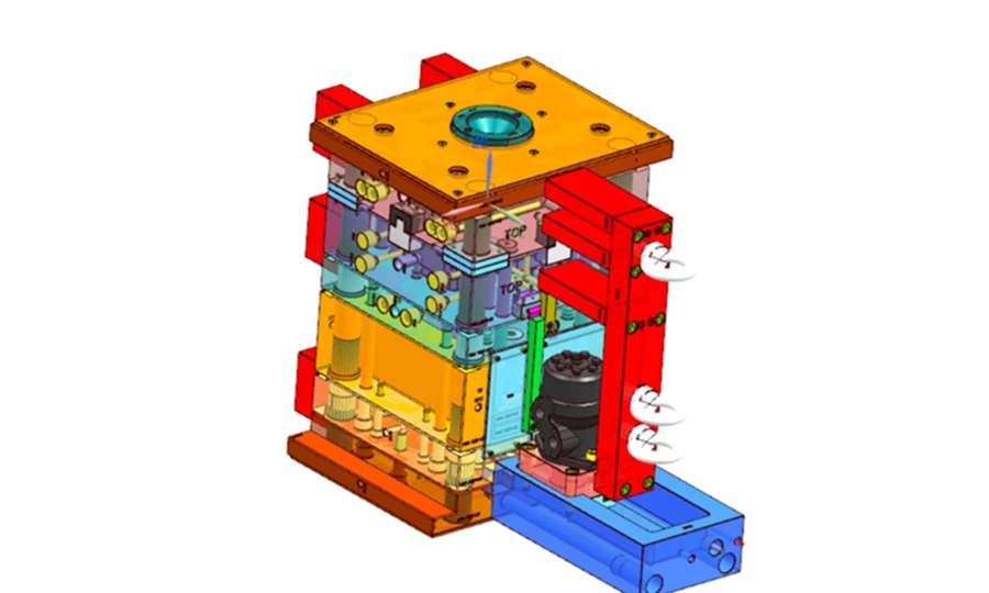
| Mold Development | H13/D2 hardened steel; PVD-coated gate inserts; oil temp control 120–160 °C; hot-runner valve gate; Moldflow pre-validated | Production-ready PPS connector tooling; guaranteed shot life |
| PPS Injection Molding | 50T–1,600T machines; dedicated oil temperature controllers; Karl Fischer moisture capability; clean cells for medical/semiconductor PPS | Precision connector production from pilot to multi-million annual |
| Post-Mold Operations | CMM pin-array mapping; secondary machining for bearing tolerances; assembly | Complete sub-assemblies with dimensional validation |
| Quality Documentation | PPAP Level 3; CoC; SPC charts; oil controller calibration records; CMM pin bore mapping; UL 94 V-0 verification | Audit-ready for automotive Tier-1 and semiconductor OEM customers |
| Supply Chain | Solvay Ryton®/Celanese Fortron®/Toray sourcing; incoming lot IV verification; DDP logistics | Traceable resin from producer to finished part |
Frequently Asked Questions
PPS plastic (polyphenylene sulfide) is a semi-crystalline high-performance thermoplastic with a repeating unit of alternating phenylene rings and sulfide linkages. It delivers continuous service temperatures to 220 °C, exceptional chemical resistance, inherent UL 94 V-0 flame resistance, and low moisture absorption (< 0.05%) — at approximately 40–60% of PEEK's raw material cost. PEEK provides higher continuous service temperature (260 °C vs. 220 °C), better low-temperature impact strength, and implant-grade biocompatibility certification — performance margins that justify PEEK's premium for applications above PPS's thermal ceiling. For the majority of automotive electrical, semiconductor process, and industrial chemical applications within 220 °C continuous service temperature, PPS plastic delivers equivalent functional performance at significantly lower program cost.
The decisive PPS benefits over PA66 for automotive connectors are: near-zero moisture absorption (PPS: < 0.05% vs. PA66: 2.5–3.5% equilibrium), which eliminates the dimensional change under humidity cycling that causes connector pin misalignment; higher HDT (40% GF-PPS: 255–270 °C vs. 30% GF-PA66: ~250 °C at 1.82 MPa, though PPS maintains stability more reliably at extended high-temperature service); inherent V-0 flame resistance without additives; and superior chemical resistance to automotive fluids at elevated temperatures. For connector programs where pin-to-pin spacing must be maintained within ±0.05 mm across all operating humidity conditions, PPS is the technically correct specification and PA66 is inadequate.
PPS plastic demonstrates excellent chemical compatibility with most industrial chemicals below 200 °C service temperature, including dilute acids (< 30% sulfuric, < 20% hydrochloric), fuels, solvents, and automotive fluids. The primary limitation is concentrated oxidizing acids at elevated temperatures: concentrated H₂SO₄ (> 30%) and concentrated HNO₃ cause surface oxidation of the sulfide groups in the PPS backbone, leading to progressive property degradation. For applications involving concentrated acid contact, PTFE or PVDF are the appropriate material specifications. Dimud conducts immersion testing per ISO 175 at service conditions for any non-standard chemical contact application before production qualification.
es — PPS plastic 3D printing is commercially available via FFF/FDM (using high-temperature all-metal hotend systems at 290–320 °C nozzle temperature) and SLS processes. However, printed PPS parts achieve only 40–80% of injection-molded PPS mechanical properties, reduced chemical resistance, and significantly wider dimensional tolerances (±0.2–0.5 mm for FFF vs. ±0.05–0.15 mm for injection molding). PPS plastic 3D printing is appropriate for design validation prototypes and one-off fixtures. For production programs requiring rated mechanical properties, chemical resistance, and dimensional precision, PPS injection molding or CNC-machined PPS sheet stock is the correct manufacturing route.
PPS injection molding requires mold temperatures of 120–160 °C to achieve the semi-crystalline structure that delivers rated mechanical properties — particularly the HDT of 255–270 °C that makes 40% GF-PPS valuable in under-hood automotive applications. At low mold temperatures (25–50 °C), PPS solidifies too rapidly for crystalline domains to develop fully, producing a low-crystallinity part with HDT of only 115–135 °C (unfilled) and reduced chemical resistance. Standard water cooling cannot achieve 120–160 °C — oil-type or pressurized water temperature controllers are required equipment for engineering-grade PPS injection molding. Dimud uses dedicated oil temperature controllers with ±2 °C stability as standard on all PPS programs.
Conclusion
PPS plastic is the rational engineering specification for every application that sits in the performance gap between standard engineering polymers (PA, PBT, POM) and ultra-high-performance materials (PEEK, PEI) — applications requiring continuous service above 180 °C, chemical resistance to aggressive fluids, inherent flame compliance, and dimensional precision that moisture-absorbing polymers cannot maintain.
The commercial case is consistent across automotive electrical, semiconductor process, industrial chemical, and energy storage applications: 40% GF-PPS delivers the thermal-chemical-electrical performance triad that the application demands, at a material cost 40–60% below PEEK and with processing parameters that a properly equipped injection molding operation can manage reliably.
The execution requirements — mold temperatures of 120–160 °C, weld-line management discipline, anisotropic shrinkage prediction for precision connector programs, and hardened tool steel throughout — are real but well-characterized. Dimud brings the process discipline, material knowledge, and tooling infrastructure to deliver PPS injection molding programs that perform to specification from DFM review through volume production qualification.