Liquid crystal polymer occupies a unique performance tier — not just high-performance, but possessing a specific combination of properties that collectively define the material: the ability to flow into walls thinner than human hair, crystallize in microseconds producing self-reinforcing molecular order, maintain dimensional stability across reflow and cryogenic temperature cycles, and deliver dielectric performance at millimeter-wave frequencies that ceramics and metals struggle to match at comparable cost and geometry complexity.
For engineers specifying components for 5G antenna modules, miniature board-to-board connectors, automotive radar sensors, medical microelectronic devices, and precision optical instrument parts, understanding LCP plastic is not optional — it is the technical foundation on which the next generation of precision miniature parts is built.
This guide covers everything: what LCP plastic material is, its LCP properties and LCP plastic material properties in detail, how LCP injection molding works in practice, LCP plastic sheet and stock shape applications, industry use cases, and how LCP compares to PPS, PEEK, and other high-performance competitors. Every section draws on Dimud’s production experience processing liquid crystal polymer across miniature electronics connector, automotive sensor, and medical microdevice programs for customers in Europe, North America, and the Middle East.
What Is LCP Plastic?
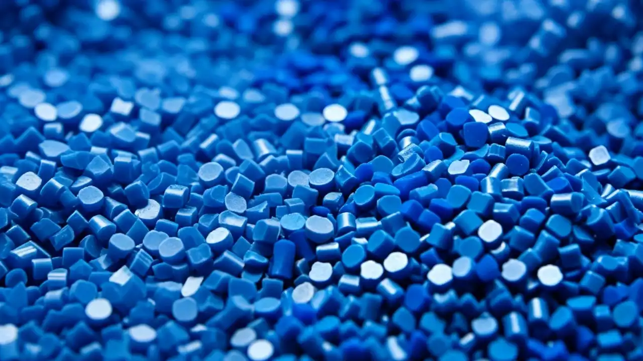
LCP plastic — liquid crystal polymer — is a family of aromatic polyester thermoplastics characterized by a rigid-rod molecular architecture that produces ordered, liquid-crystalline domains in both the melt and solid states. Unlike conventional polymers whose chains adopt random-coil conformations in the melt, LCP molecular chains maintain a high degree of parallel alignment — a structural feature that makes LCP’s processing and performance fundamentally different from every other commercial thermoplastic.
The term “liquid crystal polymer” describes this dual-phase behavior precisely: the material is liquid (flows under injection molding conditions) while maintaining crystalline molecular order (the chains stay aligned). When the melt enters the mold cavity, the shear forces of flow further align the chains in the fill direction — and rapid crystallization locks this alignment in place during solidification, creating a molecular composite where the polymer chains themselves function as reinforcing elements.
The structural basis of LCP plastic’s unique properties:
LCP molecules are built from aromatic monomers (typically combinations of hydroxybenzoic acid, hydroxynaphthoic acid, terephthalic acid, and aromatic diols) connected through ester linkages in a fully aromatic backbone. The aromatic rings are rigid, planar, and pack efficiently in parallel alignment. This molecular architecture simultaneously produces:
- Ultra-low melt viscosity: LCP melt viscosity at processing temperature is 10–50× lower than PPS or PA66 at equivalent temperature — enabling flow into walls as thin as 0.1–0.15 mm that no other thermoplastic achieves
- Rapid crystallization: LCP crystallizes within milliseconds of mold contact — enabling cycle times 20–40% shorter than PPS or PEEK at equivalent complexity
- Intrinsic self-reinforcement: Aligned molecular chains in the flow direction create directional mechanical properties without fiber addition — the polymer itself is the reinforcement
- Near-zero moisture absorption: < 0.02% water absorption (24h) — dimensional stability in humid electronics environments that PPS (0.02–0.05%) and PA66 (2.5–3.5%) cannot match
- Inherent flame resistance: UL 94 V-0 at wall thicknesses down to 0.1 mm without any flame-retardant additives — the most demanding thin-wall flame compliance in commercial thermoplastics
What liquid crystal polymer is not: LCP plastic is not a general-purpose material. Its anisotropic mechanical properties (significantly weaker in the transverse direction relative to flow), sensitivity to knit lines, and material cost ($20–$60/kg versus $3–8/kg for ABS) limit it to applications where its unique performance combination is genuinely required. Within that envelope, no other material comes close.
At Dimud, LCP plastic programs are concentrated in precision miniature connector bodies, automotive millimeter-wave radar sensor housings, 5G antenna module components, and medical microelectronic device parts — applications where the wall thickness, dimensional precision, thermal, and dielectric requirements eliminate every alternative.
LCP Plastic Material Properties: The Complete Data Profile
Understanding LCP plastic properties requires appreciation of one fundamental distinction from isotropic polymers: LCP properties are direction-dependent. The self-reinforcing molecular alignment that gives LCP its extraordinary flow-direction strength simultaneously creates weakness perpendicular to flow — a consequence that determines how LCP parts must be designed and gated.
LCP Properties — Mechanical
| Property | Unfilled LCP | 30% GF-LCP | 45% GF+Mineral LCP | Test Standard |
|---|---|---|---|---|
| Density | 1.40–1.45 g/cm³ | 1.61–1.67 g/cm³ | 1.70–1.80 g/cm³ | ISO 1183 |
| Tensile Strength (flow direction) | 180–230 MPa | 160–210 MPa | 140–180 MPa | ISO 527 |
| Tensile Strength (transverse) | 35–60 MPa | 50–80 MPa | 55–85 MPa | ISO 527 |
| Flexural Modulus (flow) | 9,000–14,000 MPa | 14,000–20,000 MPa | 16,000–22,000 MPa | ISO 178 |
| Flexural Modulus (transverse) | 6,000–9,000 MPa | 8,000–12,000 MPa | 9,000–14,000 MPa | ISO 178 |
| Notched Izod Impact | 25–60 J/m | 40–80 J/m | 40–70 J/m | ISO 180 |
| Elongation at Break (flow) | 1.5–3.5 % | 1.0–2.0 % | 0.8–1.5 % | ISO 527 |
LCP Plastic Properties — Thermal
| Property | Unfilled LCP | 30% GF-LCP | Test Standard |
|---|---|---|---|
| Heat Deflection Temp (1.82 MPa) | 180–280 °C | 240–320 °C | ISO 75 |
| Continuous Service Temperature | 200–240 °C | 220–260 °C | UL 746B |
| Peak Reflow Compatibility | 260–300 °C | 260–300 °C | J-STD-020 |
| Melting Point (Tm) | 280–360 °C | 280–360 °C | DSC |
| Coefficient of Thermal Expansion (flow) | 0–10 × 10⁻⁶/°C | 0–8 × 10⁻⁶/°C | ISO 11359 |
| Coefficient of Thermal Expansion (transverse) | 30–50 × 10⁻⁶/°C | 20–35 × 10⁻⁶/°C | ISO 11359 |
| Flammability | UL 94 V-0 (to 0.1 mm) | UL 94 V-0 | UL 94 |
| Limiting Oxygen Index | 35–45 % | 38–50 % | ISO 4589 |
LCP Plastic Properties — Electrical and Dimensional
| Property | Unfilled LCP | 30% GF-LCP | Test Standard |
|---|---|---|---|
| Dielectric Constant (1 GHz) | 2.9–3.2 | 3.2–3.8 | IEC 60250 |
| Dielectric Constant (10 GHz) | 2.9–3.1 | 3.1–3.6 | IEC 60250 |
| Dissipation Factor (1 GHz) | 0.002–0.004 | 0.003–0.006 | IEC 60250 |
| Dissipation Factor (10 GHz) | 0.002–0.005 | 0.003–0.007 | IEC 60250 |
| Dielectric Strength | 20–30 kV/mm | 18–25 kV/mm | IEC 60243 |
| Water Absorption (24h) | < 0.02 % | < 0.02 % | ISO 62 |
| Mold Shrinkage (flow) | 0.0–0.3 % | 0.0–0.2 % | ISO 294-4 |
| Mold Shrinkage (transverse) | 0.5–1.5 % | 0.3–0.8 % | ISO 294-4 |
Dimud Engineering Note — The Dielectric Advantage at High Frequency
LCP plastic’s dielectric constant stability across frequency (2.9–3.2 from 1 MHz to 10 GHz for unfilled grades) is the property that makes it irreplaceable in 5G and millimeter-wave applications. Most engineering thermoplastics show increasing dielectric constant and dissipation factor as frequency rises toward the GHz range — LCP’s rigid-rod molecular structure resists polarization even at millimeter-wave frequencies, maintaining signal integrity in antenna modules and high-frequency connector bodies where competing materials introduce unacceptable signal loss. In 5G sub-6 GHz and 24–77 GHz automotive radar programs, this property alone justifies the LCP specification.
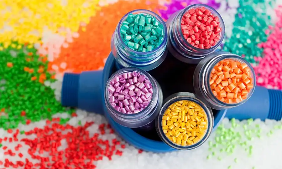
Grade Landscape: Type I, II, III and Reinforced LCP
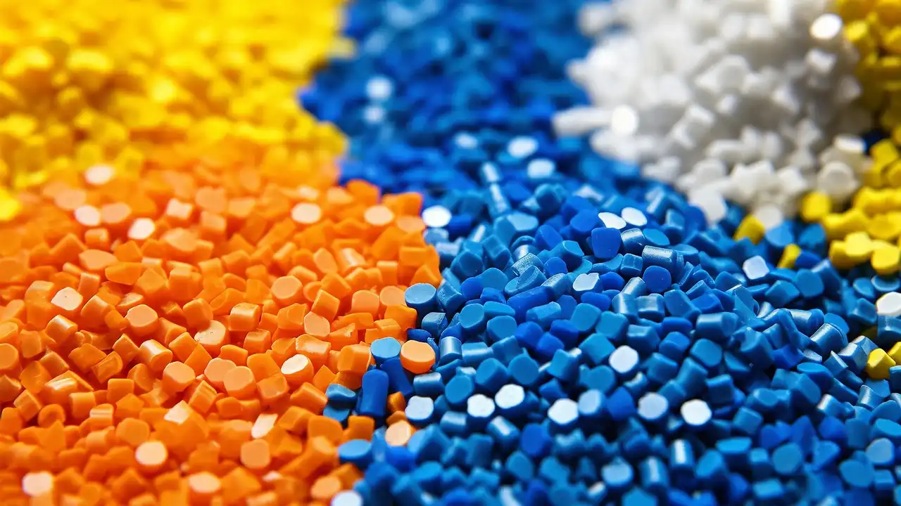
LCP Type Classification
The LCP plastic material family is classified into three types based on molecular structure and thermal performance:
| Type | Melting Point | Continuous Service | Key Structural Feature | Primary Application |
|---|---|---|---|---|
| Type I | 280–310 °C | 200–220 °C | All-aromatic backbone (e.g. HBA/HNA copolymers) | Highest performance; aerospace; specialty |
| Type II | 280–330 °C | 220–240 °C | Aromatic with limited aliphatic segments | Automotive; electronics; standard connector |
| Type III | 300–350 °C | 240–260 °C | Extended aromatic with stiff-chain segments | 5G antenna; high-temp electronics; radar |
For commercial injection molding programs at Dimud, Type II and Type III LCP are the dominant specifications — Type II for standard automotive connector and SMD component programs, Type III for 5G antenna modules and millimeter-wave radar sensor housings.
Unfilled LCP (Natural Grade)
The base grade: maximum chemical resistance, best dielectric properties, lowest density, and highest anisotropy ratio (flow vs. transverse properties). Used for precision thin-wall components where dielectric performance and chemical resistance are the primary drivers and structural loading is modest.
Glass Fiber Reinforced LCP (GF-LCP)
10–50% glass fiber reduces anisotropy, improves transverse strength and modulus, and increases dimensional isotropy at the cost of slightly reduced dielectric performance. Most commercial LCP injection molding programs for electronic connectors and automotive sensors use 30–45% GF-LCP to balance structural performance with dimensional stability.
Mineral and Hybrid Filled LCP
Glass + mineral hybrid grades (30% GF + 15% mineral typical) provide maximum dimensional isotropy — essential for flat LCP components (LED reflectors, precision housings) where differential flow/transverse shrinkage would otherwise cause warpage. Mineral filling increases density but significantly improves flatness and reduces weld-line sensitivity.
Specialty LCP Grades
| Grade | Modification | Key Benefit | Application |
|---|---|---|---|
| Plating-grade LCP | Controlled surface morphology | Electroless copper adhesion | Antenna metallization, MID (molded interconnect devices) |
| Thermally conductive LCP | Boron nitride or AlN filler | Thermal conductivity 1–5 W/m·K | LED COB package housings, power electronics |
| Low-Dk LCP | Modified monomer composition | Dielectric constant < 2.8 at 10 GHz | 5G mmWave antenna substrates |
| ESD-dissipative LCP | Carbon additives | Static dissipation | Semiconductor handling fixtures |
| Low-warpage LCP | Optimized filler morphology | Flatness < 0.1 mm on 50 mm panel | LED reflectors, camera module housings |
Key commercial brands: Vectra® (Celanese), Xydar® (Solvay), Sumikasuper® (Sumitomo Chemical), Zenite® (DuPont/Celanese), Siveras® (Toray).
LCP Injection Molding: Process Parameters and Unique Challenges
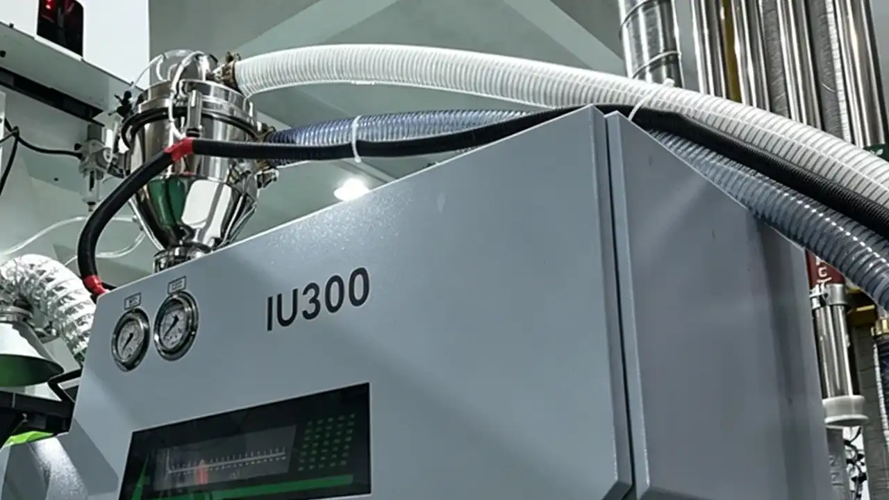
LCP injection molding is operationally similar to PPS or PEEK processing in terms of barrel temperature requirements, but presents unique challenges that no other commercial thermoplastic imposes: the same ultra-low viscosity that enables thin-wall filling also creates an extreme flash tendency, and the rapid crystallization that enables short cycle times also creates premature freeze-off risk in cold runner systems if injection parameters are not precisely controlled.
The Unique Challenges of LCP Injection Molding
Ultra-low melt viscosity — the double-edged property: LCP’s melt viscosity at processing temperature is 10–50× lower than most engineering polymers. This enables thin-wall filling that no alternative polymer achieves — but also means flash generation is catastrophic if parting line fit is not maintained to < 0.01 mm. LCP flash penetrates parting line gaps that would be inconsequential with PA or PBT. Dimud specifies tight parting line tolerances and hardened tool steel for all LCP injection molding programs as a standard requirement.
Rapid crystallization — the cycle time advantage with freeze-off risk: LCP crystallizes within milliseconds of contacting the mold wall. This enables cycle times 20–40% shorter than PPS at equivalent part size. However, in cold runner systems, the runner itself can freeze before the cavity is filled in multi-cavity tools — requiring either hot-runner systems or carefully sized runner cross-sections with barrel temperature profiles calibrated to prevent premature crystallization in the runner.
Anisotropic shrinkage — the warpage driver: Flow-direction shrinkage in LCP injection molding is near-zero (0.0–0.3%). Transverse shrinkage is 0.5–1.5%. This differential creates high warpage risk in any flat or asymmetric LCP component without careful gate design, balanced fill, and filler selection.
Weld-line weakness — the structural limitation: LCP’s ordered molecular alignment is disrupted at weld lines, where two flow fronts meet with chains oriented in conflicting directions. Weld-line tensile strength is typically 30–50% of parent material — the lowest retention of any commercial injection-molding polymer. Every LCP injection molding program at Dimud includes mandatory Moldflow weld-line analysis before tool design is finalized.
Drying Protocol
LCP plastic material’s water absorption is among the lowest of all polymers (< 0.02% at 24h). Despite this, drying is required:
| Parameter | Standard LCP | Type III / High-Performance LCP | Regrind LCP |
|---|---|---|---|
| Dryer type | Dehumidifying hopper | Dehumidifying hopper | Dehumidifying hopper |
| Temperature | 120–150 °C | 140–160 °C | 120–140 °C |
| Duration | 3–4 hours | 4–5 hours | 2–3 hours |
| Target moisture | < 0.02 % | < 0.01 % | < 0.02 % |
| Max regrind ratio | 15–20 % | 10 % | — |
Barrel and Melt Temperature
LCP plastic’s melting point depends on type (280–360 °C), and barrel temperatures must be set above the melting point to achieve the ultra-low-viscosity melt required for thin-wall filling:
| Zone | Type II LCP | Type III LCP | Notes |
|---|---|---|---|
| Rear (Feed) | 270–300 °C | 290–320 °C | Controlled entry; no cold plugs |
| Middle (Compression) | 295–330 °C | 320–355 °C | Primary melting zone |
| Front (Metering) | 305–345 °C | 335–365 °C | Low-viscosity melt target |
| Nozzle | 300–340 °C | 330–360 °C | Heated nozzle mandatory; reverse-taper design |
Critical requirement: LCP injection molding requires a heated nozzle — unlike most thermoplastics where nozzle insulation is sufficient, LCP’s rapid crystallization causes cold slug formation in unheated nozzles that produces black specks and short shots. Dimud specifies heated open-tip nozzles on all LCP programs.
Mold Temperature
LCP injection molding mold temperature: 70–120 °C
- 70–90 °C: Standard for miniature connector programs where cycle time is the priority; adequate for 30% GF-LCP dimensional stability
- 90–110 °C: Recommended for precision optical and antenna components requiring maximum dimensional isotropy; reduces warpage in flat LCP panels
- 110–120 °C: Used for Type III LCP programs and for parts requiring maximum crystallinity development
LCP does not require the extreme mold temperatures of PEEK (160–200 °C) — a process advantage that allows standard hot-water temperature controllers to be used for most LCP programs.
Injection Speed and Pressure — The LCP Paradox
LCP injection molding requires fast injection — counterintuitive for engineers familiar with high-performance polymers like PEEK where slow fill is critical:
- Injection pressure: 80–160 MPa (high; necessary to overcome the nozzle pressure drop before LCP reaches its ultra-low-viscosity flow regime in the cavity)
- Injection speed: Fast to very fast — LCP’s rapid crystallization means the mold fills in < 0.5 seconds on most miniature connector programs; slow injection allows premature freeze-off in thin sections
- Hold pressure: 30–50% of injection pressure (lower than most polymers; LCP’s low shrinkage means minimal packing is required)
- Back pressure: 5–10 MPa (very low; excessive back pressure destroys molecular order in LCP melt)
Common LCP Injection Molding Defects and Solutions
| Defect | Root Cause | Corrective Action |
|---|---|---|
| Flash | Parting line gap > 0.01 mm; over-injection | Tight P/L fit (< 0.005 mm); reduce injection speed at end of fill; optimize velocity-pressure transfer |
| Short shot / premature freeze | Cold runner; injection speed too slow; barrel temp too low | Hot-runner system; increase barrel temp; increase injection speed |
| Weld lines (weak / visible) | Multi-gate fill convergence; flow obstruction | Consolidate gates; optimize gate position; raise melt temp |
| Warpage (flat parts) | Anisotropic shrinkage; asymmetric fill | Balanced fill; hybrid GF+mineral grade; multiple gates |
| Black specks / contamination | Cold slug in nozzle; thermal degradation | Heated nozzle; reduce residence time; purge between runs |
| Fiber exposure on surface | Mold temp too low; excessive shear at gate | Raise mold temp to 100 °C+; reduce gate shear |
| Delamination | Excessive shear; barrel temperature too low | Reduce injection speed; raise barrel temp uniformly |
| Dimensional variation (transverse) | Anisotropic shrinkage inconsistency | Stabilize mold temp ±2 °C; balanced fill analysis |
Mold Design Considerations for LCP Plastic Components
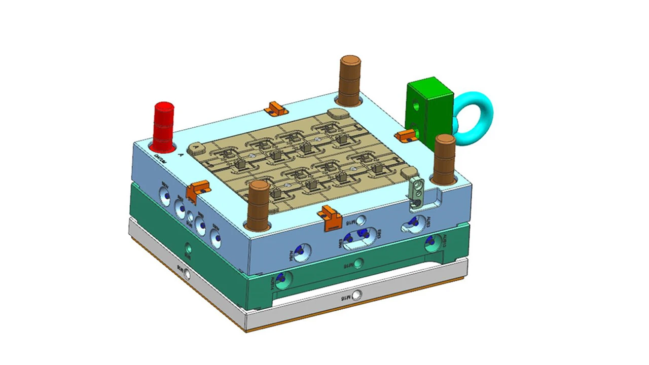
LCP injection molding imposes the most demanding parting line and gate design requirements of any commercial thermoplastic — consequences of the ultra-low melt viscosity that simultaneously enables LCP’s thin-wall advantage and creates its most difficult tooling challenges.
Parting Line Fit — The Most Critical LCP Tooling Requirement
LCP melt viscosity is so low that it penetrates parting line gaps that are inconsequential for all other thermoplastics. Standard parting line fit tolerances (0.02–0.05 mm) that prevent flash in PA or PBT programs produce continuous flash in LCP tools. Dimud’s LCP tooling standard:
- Parting line fit: < 0.005 mm across entire cavity perimeter (versus 0.02 mm standard for engineering polymers)
- Steel selection: H13 hardened (50–54 HRC) minimum for all LCP programs; D2 for high-volume multi-cavity tools
- Parting line maintenance: Scheduled inspection and refitting every 50,000–80,000 shots in high-volume LCP connector programs
- Venting: Vent depth 0.005–0.015 mm maximum (versus 0.02–0.05 mm for standard polymers) — LCP flashes through standard vent depths
Gate Design for LCP Injection Molding
Gate design determines fill pattern, weld-line position, and anisotropic shrinkage distribution — the three most critical variables for LCP part quality:
- Hot-runner valve gates: Mandatory for all production LCP injection molding programs at Dimud above 2 cavities. LCP’s rapid crystallization makes cold runner temperature management impractical in multi-cavity tools; hot-runner systems maintain melt temperature uniformity from manifold to gate and enable precise valve timing to control fill dynamics
- Direct gates (single cavity): Used for large single-cavity LCP parts where gate size can be maximized to reduce shear
- Fan gates: Effective for flat LCP panels where reducing anisotropic flow orientation is critical for warpage control
- Gate size: Larger than equivalent PPS or PA programs — LCP’s low viscosity is accessed only after overcoming the initial gate pressure drop; undersized gates prevent the transition to ultra-low-viscosity flow that makes thin-wall LCP filling possible
Steel Selection
| Steel | Application | Notes |
|---|---|---|
| H13 hardened (50–54 HRC) | Standard LCP connector programs | Minimum acceptable; parting line maintenance required |
| D2 (62–64 HRC) | High-volume 48–128 cavity LCP programs | Maximum hardness for parting line durability |
| S136 stainless | Medical-grade LCP; optically polished surfaces | Corrosion resistance; SPI A1 polishability |
| H13 + PVD TiAlN coating | All gate inserts on GF-LCP programs | PVD coating mandatory for gate wear resistance |
Runner and Hot-Runner System
- Cold runners are not recommended for production LCP programs. Rapid crystallization causes runner freeze between shots in multi-cavity tools, producing inconsistent fill across cavities and short shots in remote cavities
- Hot-runner manifold: Must be rated for 380 °C service for Type III LCP; PEEK-compatible seal materials in the manifold assembly
- Valve gate tip material: H13 with PVD coating; tip geometry designed for LCP’s low-viscosity flow pattern
LCP Plastic Sheet and Stock Shape Applications
Beyond injection molding, LCP plastic sheet and film products serve important roles in electronics substrates and prototype fabrication.
LCP Plastic Sheet for Electronics Substrates
LCP plastic sheet (typically 25–200 µm thickness) is produced by extrusion or calendering processes and serves as a high-frequency dielectric substrate in flexible and rigid-flex printed circuit board applications — a growing market driven by 5G and millimeter-wave electronics demand:
- LCP flexible circuit substrates: LCP film at 25–100 µm thickness replaces polyimide (PI) in antenna circuits where PI’s higher dielectric constant (3.5 vs LCP’s 2.9–3.1 at 10 GHz) and higher dissipation factor introduce unacceptable signal loss at millimeter-wave frequencies
- 5G antenna array substrates: LCP plastic sheet at 50–200 µm is specified for phased-array antenna feed networks in 5G base station and handset mmWave modules
- Hermetic packaging substrates: LCP’s near-zero moisture absorption makes it a candidate for MEMS and sensor packaging applications where humidity-driven dimensional change would affect calibration
LCP Plastic Sheet vs. Injection Molding — When to Choose
| Criterion | LCP Plastic Sheet (Machined / Laminated) | LCP Injection Molding |
|---|---|---|
| Geometry | Flat, laminated, substrate-type | Complex 3D (connectors, housings) |
| Wall thickness | 25 µm–10 mm | 0.10 mm–10 mm |
| Volume | 1–1,000 units | > 200 units (tool amortization) |
| Primary application | RF substrates, MEMS packaging | Connectors, sensor housings, fixtures |
| Dimensional control | ±0.010–0.050 mm (machined) | ±0.020–0.100 mm (molded) |
For precision LCP connector programs, injection molding is the cost-effective production route. For high-frequency substrate applications, LCP plastic sheet in film or extruded form is the appropriate product form.
Self-Reinforcement: LCP's Defining Manufacturing Advantage

Self-reinforcement is the property that makes LCP plastic material fundamentally different from every other commercial thermoplastic — and the property that product engineers must understand to correctly leverage LCP in program design.
How Self-Reinforcement Works
When LCP plastic melt enters the mold cavity, shear forces align the rigid-rod molecular chains in the flow direction. As the material crystallizes (within milliseconds), this alignment is locked in place. The result is a part in which the polymer chains themselves act as unidirectional fiber reinforcement — without any fiber addition.
The consequence for engineering: an unfilled LCP part has flexural modulus in the flow direction of 9,000–14,000 MPa — comparable to 30% glass-fiber-filled PA66 (approximately 9,000 MPa). This is not filler-reinforced performance — it is the intrinsic molecular architecture performing as structural reinforcement.
Engineering Implications of Self-Reinforcement
- Thin-wall structural integrity: LCP’s self-reinforced stiffness enables connector walls of 0.15–0.30 mm to maintain positional stability under pin insertion forces — a structural performance level that requires 50%+ glass fiber loading in competing materials to approximate
- Net-shape precision: Because LCP’s self-reinforcement develops during injection molding rather than requiring post-mold processing, the as-molded part dimension IS the final dimension — no shrinkage correction or thermal treatment required
- Fiber loading trade-offs: Adding glass fiber to LCP reduces the anisotropy ratio (improves transverse properties) but does not proportionally increase flow-direction strength — because the unfilled grade already captures most of the available molecular reinforcement. The primary function of glass fiber in LCP programs is warpage reduction through improved dimensional isotropy, not structural performance improvement
LCP Industry Applications
Consumer Electronics and 5G Infrastructure
Consumer electronics — specifically miniature connector bodies, antenna modules, and sensor housings in smartphones, IoT devices, and 5G infrastructure equipment — is the largest and fastest-growing application domain for LCP plastic.
Board-to-board and FPC connectors (30–45% GF-LCP): The global miniature connector market has converged on LCP as the dominant housing material for pitches below 0.5 mm. LCP’s ultra-low-viscosity melt enables filling of 0.1–0.2 mm wall sections that surround 0.3–0.4 mm pin pitches — no competing thermoplastic achieves this geometry at production quality. LCP’s reflow solder compatibility (260 °C peak; LCP melting points 280–360 °C) eliminates the connector housing deformation that disqualifies PA, PBT, and LDS-capable but lower-HDT materials from these programs.
Dimud produces LCP connector bodies in 30–45% GF-LCP to IPC/JEDEC J-STD-020 reflow compatibility requirements with PPAP-equivalent dimensional documentation as standard deliverables. For our full electronics manufacturing capabilities, see our Electronics & Semiconductor industry page.
5G mmWave antenna modules (Type III LCP / Low-Dk LCP): Phased-array antenna modules for 5G sub-6 GHz and 24–77 GHz millimeter-wave applications require antenna housing materials with dielectric constants ≤ 3.2 and dissipation factors ≤ 0.005 at 10–77 GHz — specifications that PPS, PA, and most engineering thermoplastics cannot meet. LCP injection-molded antenna housings and substrate components are the dominant specification in this application, and the foundation for continued 5G infrastructure buildout.
Smartphone camera module housings (low-warpage LCP): Camera module housings in smartphones must maintain flatness < 0.05 mm on components measuring 8–15 mm across — with dimensions stable from −40 °C to +85 °C through thermal cycling. LCP’s near-zero CTE in the flow direction and low moisture absorption enable this dimensional stability without the secondary operations (post-mold fixturing, annealing) required for competing materials.
LED reflector cups (hybrid GF+mineral LCP): LED COB (chip-on-board) reflector cups requiring high reflectance, dimensional stability at LED junction temperatures (150–180 °C continuous), and reflow process compatibility. LCP’s inherent brightness, thermal stability, and reflow compatibility make it the dominant material for LED reflector applications globally.
Automotive
Automotive radar sensor housings — 76–77 GHz and 24 GHz (Type III LCP): Short-range and long-range automotive radar sensors for ADAS (advanced driver assistance systems) require sensor housing materials with dielectric properties stable across the operating temperature range (−40 °C to +125 °C), dimensional stability to maintain beam-pointing accuracy over the vehicle life, and sufficient thermal resistance for SMD-compatible assembly. Type III LCP satisfies all requirements simultaneously — a specification now standard across major Tier-1 automotive radar sensor OEMs.
Precision electrical connector bodies (30–45% GF-LCP): High-voltage EV powertrain connectors, automotive Ethernet connector housings (USCAR-2 compliant), and miniature ECU connector bodies where pin pitch below 1.0 mm and reflow or soldering compatibility are concurrent requirements. LCP’s dimensional stability across −40 °C to +125 °C operating temperature range, combined with UL 94 V-0 flame compliance, makes it the technical specification for compact precision automotive connectors.
Engine and gearbox sensor components (Type II LCP): Crankshaft position sensors, camshaft sensors, and transmission speed sensors require housings that maintain dimensional precision at engine operating temperatures (continuous: 150 °C; peak: 200 °C) while resisting fuels, transmission fluids, and gear oils. LCP’s chemical resistance and thermal performance address these requirements at production-volume economics.
Medical Devices
Surgical instrument miniature connectors and cable assemblies (medical-grade LCP): Endoscopic instrument connectors, catheter shaft connectors, and laparoscopic tool electrical interfaces. Medical-grade LCP with USP Class VI and ISO 10993 certification provides the combination of miniature geometry capability, steam autoclave compatibility (134 °C, repeated cycles), chemical resistance to surgical disinfectants, and dimensional precision required for surgical instrument interconnect applications.
Implantable device hermetic packaging components (specialized LCP): LCP’s near-zero moisture absorption, biocompatibility, and dimensional stability have attracted interest for implantable medical device packaging — particularly for cochlear implant and neurostimulator housings where traditional titanium enclosures can be replaced with LCP for reduced mass and MRI compatibility. This remains an emerging application with active clinical evaluation underway.
Diagnostic and laboratory microfluidic components (standard / medical LCP): MEMS-integrated microfluidic platforms for point-of-care diagnostics increasingly specify LCP for device body components where dimensional precision at the 10–50 µm channel scale and chemical resistance to biological assay reagents are simultaneously required.
For our medical manufacturing capabilities, see our Medical & Healthcare injection molding page.
Industrial and Robotics
Precision encoder and resolver housings (30% GF-LCP): Rotary encoder components in servo motor assemblies require housing materials that maintain bearing seat dimensional tolerances (±0.010–0.025 mm) across −40 °C to +120 °C operating temperature range. LCP’s low and predictable shrinkage enables these tolerances in injection-molded net-shape production — eliminating the post-mold machining required for competing materials.
Robot joint connector and sensor interface components (GF-LCP): Miniature connectors for servo motor power and encoder feedback in collaborative robot joint assemblies. The combination of 0.5 mm pitch connector compatibility, reflow assembly process capability, and continuous service at motor operating temperatures (120–150 °C) converges on LCP as the specification for next-generation collaborative robot joint interface electronics.
High-temperature industrial sensor housings (Type III LCP): Pressure sensors, flow sensors, and temperature transducers deployed in industrial process environments at continuous temperatures above 200 °C. Type III LCP’s continuous service temperature (240–260 °C) combined with chemical resistance to process chemicals enables sensor housings that replace sintered metal or ceramic alternatives at injection-molding production economics.
LCP Plastic vs. Competing High-Performance Materials
| Property | LCP | PPS (40% GF) | PEEK (unfilled) | LDS-PA (for MID) | Ceramic |
|---|---|---|---|---|---|
| Thin-wall capability (min. wall) | ★★★★★ (0.1 mm) | ★★★☆☆ (0.8 mm) | ★★★☆☆ (1.0 mm) | ★★★☆☆ (0.5 mm) | ★★☆☆☆ |
| Reflow solder compatibility (260 °C) | ★★★★★ | ★★★★☆ | ★★★★★ | ★★★☆☆ | ★★★★★ |
| Dielectric at GHz frequencies | ★★★★★ | ★★★☆☆ | ★★★★☆ | ★★☆☆☆ | ★★★★☆ |
| Dimensional stability (moisture) | ★★★★★ | ★★★★★ | ★★★★☆ | ★★★☆☆ | ★★★★★ |
| Inherent flame resistance | ★★★★★ (V-0 @ 0.1mm) | ★★★★★ | ★★★★★ | ★★★☆☆ | N/A |
| Isotropic mechanical properties | ★★☆☆☆ | ★★★★☆ | ★★★★★ | ★★★★☆ | ★★★★★ |
| Weld-line strength | ★★☆☆☆ | ★★★☆☆ | ★★★☆☆ | ★★★★☆ | N/A |
| Processing ease | ★★★☆☆ | ★★★★☆ | ★★☆☆☆ | ★★★★☆ | ★☆☆☆☆ |
| Raw material cost | $$$ High | $$ Medium | $$$$$ Very High | $$ Medium | |
| Flash sensitivity | ★☆☆☆☆ (extreme) | ★★★☆☆ | ★★★☆☆ | ★★★★☆ | N/A |
LCP vs. PPS: PPS is more isotropic, has better weld-line strength, and is less flash-sensitive — making PPS the appropriate specification for structural components without extreme thin-wall or high-frequency dielectric requirements. LCP wins decisively where wall thickness below 0.5 mm is required, where GHz-range dielectric performance must be maintained, or where reflow solder assembly requires > 260 °C peak temperature compatibility at thin walls. For standard automotive connectors with pin pitch above 1.0 mm and walls above 0.5 mm, PPS remains the cost-optimized specification.
LCP vs. PEEK: PEEK provides better isotropic mechanical properties, superior biocompatibility certification, and higher continuous service temperature (260 °C vs LCP’s 220–240 °C for most grades). LCP wins on thin-wall capability, dielectric performance at GHz frequencies, moisture absorption (LCP < 0.02% vs PEEK 0.50%), and reflow process compatibility at thin walls. For miniature electronics connector and antenna applications, LCP’s property combination is purpose-built for the application; PEEK’s superior structural performance is not utilized.
For a comprehensive comparison across Dimud’s full high-performance polymer portfolio, see the injection molding materials guide.
DFM Guidelines for LCP Plastic Parts
LCP injection molding DFM requires specific attention to the material’s unique failure modes — weld-line weakness, anisotropic shrinkage-driven warpage, and flash generation — that differ fundamentally from the DFM concerns of isotropic engineering polymers.
Dimud’s Product Design & DFM service includes Moldflow weld-line analysis, anisotropic shrinkage prediction, and flash-risk assessment as standard deliverables for all LCP programs.
Wall Thickness
LCP’s thin-wall capability is its defining commercial advantage — but minimum wall thickness is bounded by gate pressure delivery capability and weld-line structural requirements:
- Minimum wall: 0.10–0.15 mm for unfilled LCP with hot-runner and optimized gate; 0.20–0.30 mm for GF-LCP
- Recommended minimum for structural sections: 0.30 mm (provides adequate weld-line strength margin)
- Maximum wall: No practical upper limit — LCP’s rapid crystallization enables thick walls without void formation
Uniform wall thickness is critical for warpage control. Differential shrinkage between thick and thin LCP sections (flow direction: near-zero; transverse: 0.5–1.5%) is amplified by thickness variation.
Weld-Line Management — The LCP Design Priority
Weld-line placement is the single most critical DFM variable for LCP structural programs. Rules at Dimud:
- Gate positions selected to place weld lines in non-structural zones — never through hole walls, never at snap-fit roots, never through bearing surfaces
- All structural weld line locations validated by Moldflow simulation before tool design freeze
- Weld-line tensile strength testing (ISO 527 on weld-line specimens) conducted on T1 samples before production approval on all LCP structural programs
Corner Radii
Minimum internal corner radius: 0.1 mm for thin-wall LCP; 0.5 mm for structural sections.
LCP’s inherent brittleness (elongation at break: 1.5–3.5%) makes sharp corners fracture initiation sites under mechanical loading. For LCP connector programs subjected to repeated insertion-extraction loading, all internal corners at structural elements carry minimum 0.3 mm radius in Dimud’s standard.
Draft Angles
- Standard surfaces: 0.5°–1.0° per side (lower than for stiff polymers like PPS — LCP’s low transverse shrinkage reduces grip on the core)
- Polished surfaces: 0.5° per side minimum
- Textured surfaces: 1.0°–2.0° per side depending on texture depth
Achievable Tolerances
LCP plastic injection molding enables the tightest dimensional tolerances of any commercial thermoplastic:
- Flow direction (GF-LCP): ±0.010–0.030 mm on critical connector pin bore dimensions
- Transverse direction: ±0.030–0.080 mm (higher shrinkage requires wider tolerance without compensating gate design)
- Pin pitch tolerance on 0.4 mm pitch LCP connectors: ±0.020 mm achievable with Moldflow-pre-validated tooling and SPC process control
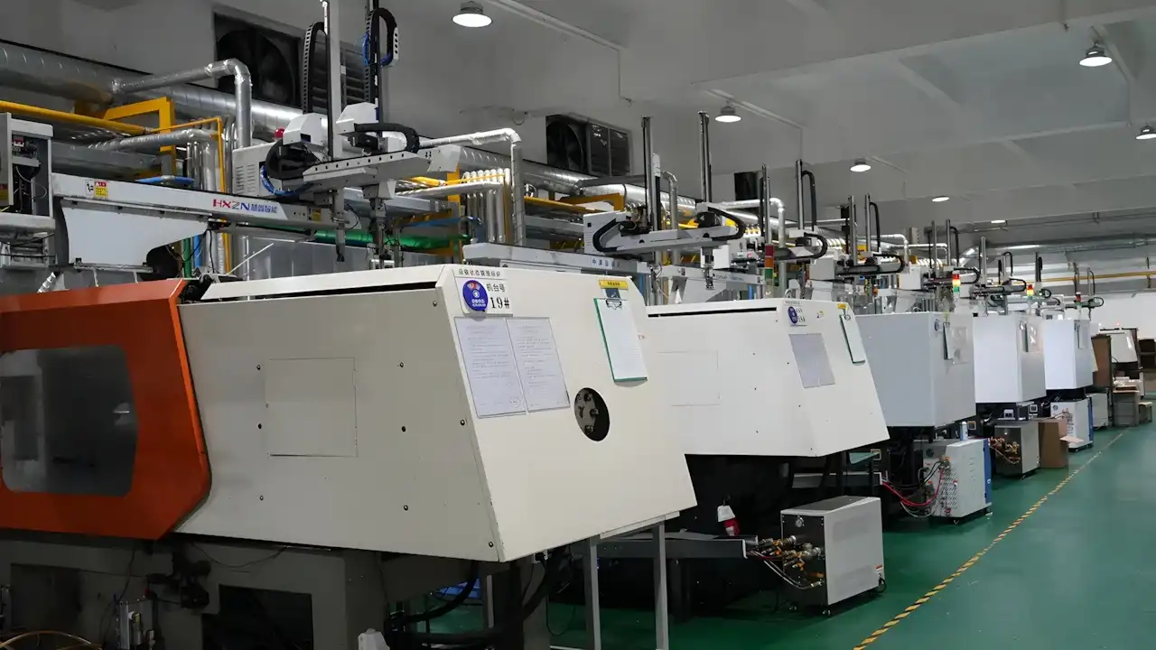
Dimud's LCP Plastic Injection Molding Capabilities
Dimud provides LCP injection molding as part of a vertically integrated manufacturing system — three coordinated plants covering mold development, CNC machining, and electronics assembly — serving consumer electronics, automotive, medical, and industrial robotics customers in Europe, North America, and the Middle East.
| Service Stage | Dimud Capability | Customer Benefit |
|---|---|---|
| DFM & Grade Review | Type selection (I/II/III); weld-line Moldflow analysis; anisotropic shrinkage prediction; flash risk assessment | Eliminate the most common LCP connector program failures before tooling |
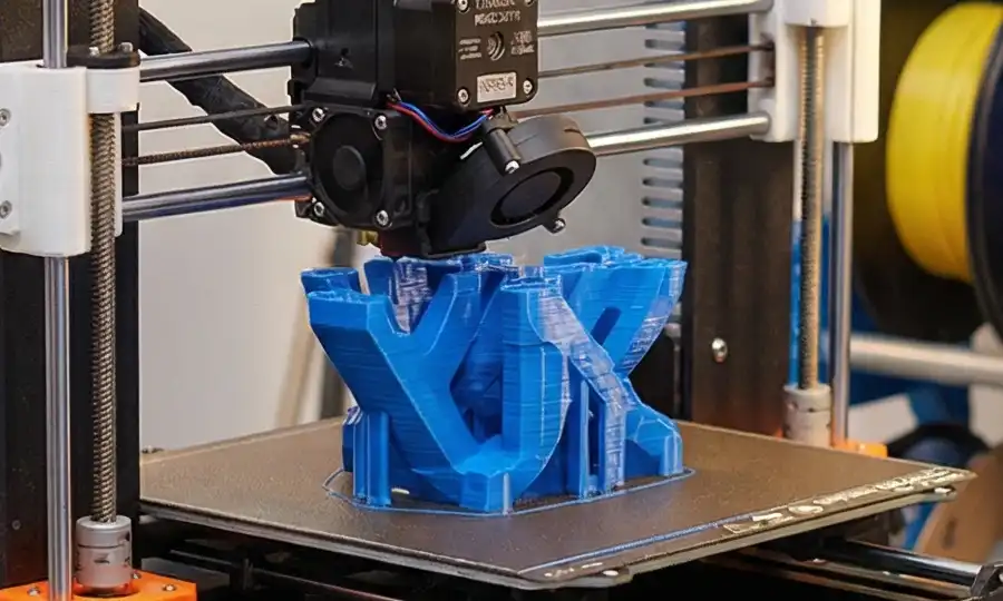
| Rapid Prototyping | CNC-machined LCP sheet samples + aluminum soft tools for connector verification | Engineering samples in 10–15 working days |
| Mold Development | H13/D2 hardened steel; parting line fit < 0.005 mm standard; hot-runner valve gate (LCP-rated manifold); PVD-coated gate inserts; Moldflow pre-validated | Production-ready LCP connector tooling; guaranteed parting line maintenance schedule |
| LCP Injection Molding | 50T–600T machines; heated nozzle systems; hot-water temp controllers 70–120 °C; fast-response injection control | Precision thin-wall LCP production from pilot to multi-million annual |
| Quality Inspection | CMM pin-pitch and bore mapping; J-STD-020 reflow simulation; UL 94 V-0 lot verification | Connector-grade dimensional documentation on every production lot |
| Quality Documentation | PPAP Level 3; CoC; CMM pitch/bore maps; reflow test records; UL 94 certificates; RoHS/REACH declarations | Audit-ready for electronics OEM, automotive Tier-1, and medical OEM customers |
| Supply Chain | Celanese Vectra®/Solvay Xydar®/Toray Siveras® resin sourcing; incoming lot verification; DDP logistics | Traceable resin from approved producers to finished connector body |
FAQ
LCP plastic (liquid crystal polymer) is an aromatic polyester thermoplastic whose molecular chains maintain ordered, liquid-crystalline alignment in both melt and solid states. This rigid-rod molecular architecture gives LCP a unique combination of properties: ultra-low melt viscosity enabling walls as thin as 0.1 mm, near-zero moisture absorption (< 0.02%), inherent UL 94 V-0 at 0.1 mm wall thickness, dielectric constant stability from MHz to GHz frequencies, and self-reinforcing molecular alignment that provides structural performance without fiber addition. The key distinction from PPS and PEEK is LCP's thin-wall capability and high-frequency dielectric performance — properties that no other commercial injection-moldable thermoplastic achieves simultaneously.
LCP plastic material properties critical for 5G include: dielectric constant of 2.9–3.2 at 10 GHz (stable to 77 GHz) — significantly lower and more stable than PPS (3.5–4.0) or PA66 (3.5–4.5) at equivalent frequencies; dissipation factor of 0.002–0.005 at 10 GHz — enabling low signal loss in antenna housing and substrate applications; near-zero moisture absorption (< 0.02%) — ensuring dimensional stability and dielectric property consistency in outdoor and variable-humidity 5G installations; and reflow solder compatibility at 260 °C — enabling standard SMD assembly processes for 5G module integration. These LCP properties collectively define the material as the specification standard for 5G millimeter-wave antenna and connector applications.
LCP plastic sheet refers to extruded or calendered LCP film (25–200 µm) or sheet stock (0.1–10 mm) used in electronics substrate applications or CNC-machined prototype components. LCP plastic sheet in film form is the standard substrate material for flexible antenna circuits and 5G phased-array feed networks, where LCP's low dielectric constant (2.9–3.1 at 10 GHz) and low dissipation factor outperform conventional polyimide (PI) substrates. LCP sheet stock is used for engineering validation samples and low-volume precision components where injection molding tooling investment is not warranted. For production quantities above 200–500 annual units of connector or housing components, LCP injection molding is the cost-effective production route.
Flash prevention in LCP injection molding requires tighter parting line fit than any other commercial thermoplastic. Dimud's standard is parting line fit < 0.005 mm (versus 0.02 mm for standard engineering polymer programs) achieved through hardened H13 or D2 tool steel, precision EDM and grinding of parting line surfaces, and scheduled parting line inspection and refitting every 50,000–80,000 shots in high-volume LCP programs. Vent depth is also limited to 0.005–0.015 mm (versus 0.02–0.05 mm for standard polymers) to prevent flash through vent channels. The investment in tight tooling tolerances is a non-negotiable requirement for LCP programs — it cannot be compensated by process adjustment.
LCP's anisotropic molecular alignment creates significantly lower properties in the transverse (perpendicular to flow) direction versus the flow direction: transverse tensile strength is 35–60 MPa versus 180–230 MPa in the flow direction for unfilled LCP. This means structural loads should be aligned with the anticipated flow direction wherever possible. For applications with multidirectional loading, 30–45% glass fiber reinforced LCP provides better property isotropy while maintaining LCP's thermal and dielectric advantages. Weld lines — where two LCP flow fronts meet with chain orientation in conflicting directions — are the most critical structural vulnerability: weld-line strength retention is only 30–50% of parent material tensile strength. All LCP programs at Dimud include mandatory Moldflow weld-line analysis before tooling to ensure weld lines are positioned in non-structural zones.
Conclusion
LCP plastic — liquid crystal polymer — is one of the most precisely specialized materials in injection molding. Its performance is not broadly superior to alternatives across all dimensions; it is decisively superior in the specific combination of properties that defines the most demanding miniature electronics, high-frequency, and precision thermal applications: walls thinner than any competitor can fill, dielectric stability from MHz to millimeter-wave frequencies, near-zero moisture absorption, and reflow solder compatibility at thin walls that no other polymer sustains.
The engineering challenge is executing LCP programs with the tooling precision and process discipline the material demands — parting line fits measured in microns, hot-runner systems rated for 380 °C, Moldflow weld-line analysis before steel cutting, and quality documentation calibrated for electronics OEM and automotive Tier-1 supply chain expectations.
Dimud brings all of these capabilities to LCP plastic programs — from DFM review and grade selection through production qualification and volume delivery — for customers whose miniature connector, antenna, radar sensor, and precision industrial programs require the material’s unique performance delivered with manufacturing reliability.