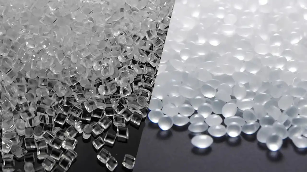
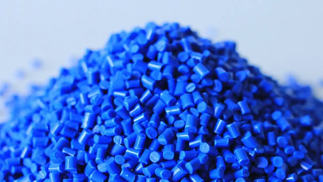
Are you looking for a material that “can be injection molded, is resistant to strong acids, and has properties similar to PTFE”? Then you should take a closer look at FEP plastic. It is one of the few members of the fluoroplastic family that can be mass-produced using standard melt processing techniques, while offering chemical inertness comparable to PTFE and optical transparency that PTFE lacks.
However, FEP plastic is not a material that can simply be used without careful consideration. It places extremely high demands on the injection molding process, has a narrow processing window, and exhibits an unusually low melt viscosity; even the slightest misstep can lead to a series of part defects. For factories without experience in fluoroplastic injection molding, the failure rate for FEP plastic is significantly higher than that of general-purpose engineering plastics.
The Dimud team has systematically accumulated process expertise in the field of high-performance fluoroplastic injection molding. This article will systematically outline the core knowledge of FEP plastic from three perspectives—materials science, engineering selection, and practical processing—to help engineers and procurement teams make informed decisions.
What is FEP Plastic?
The full name of FEP plastic is Fluorinated Ethylene Propylene, which is a copolymer of tetrafluoroethylene (TFE) and hexafluoropropylene (HFP). DuPont was the first to commercialize it in the 1960s under the brand name Teflon® FEP; since then, Daikin’s Neoflon® FEP and 3M/Dyneon’s Dyneon® FEP have become the main competing brands.
The development of FEP plastic had a clear engineering rationale: PTFE offers excellent performance but cannot be processed by melting; it can only be sintered or machined, resulting in extremely low mass production efficiency. FEP introduces HFP side chains into the TFE main chain, disrupting PTFE’s highly ordered crystalline structure to reduce melt viscosity to a level suitable for injection molding and extrusion, while retaining the vast majority of fluoroplastic properties. The HFP content typically ranges from 10% to 20% by weight; this formulation window precisely controls the crystallinity (approximately 40%–60%) and melt flow rate (MFR) of FEP plastic.
From a chemical structural perspective, FEP is a semi-crystalline perfluorinated polymer—all hydrogen atoms on the main chain and side groups are replaced by fluorine atoms, and the bond energy of the C–F bond is approximately 485 kJ/mol, which is the fundamental reason for its extremely high chemical inertness.
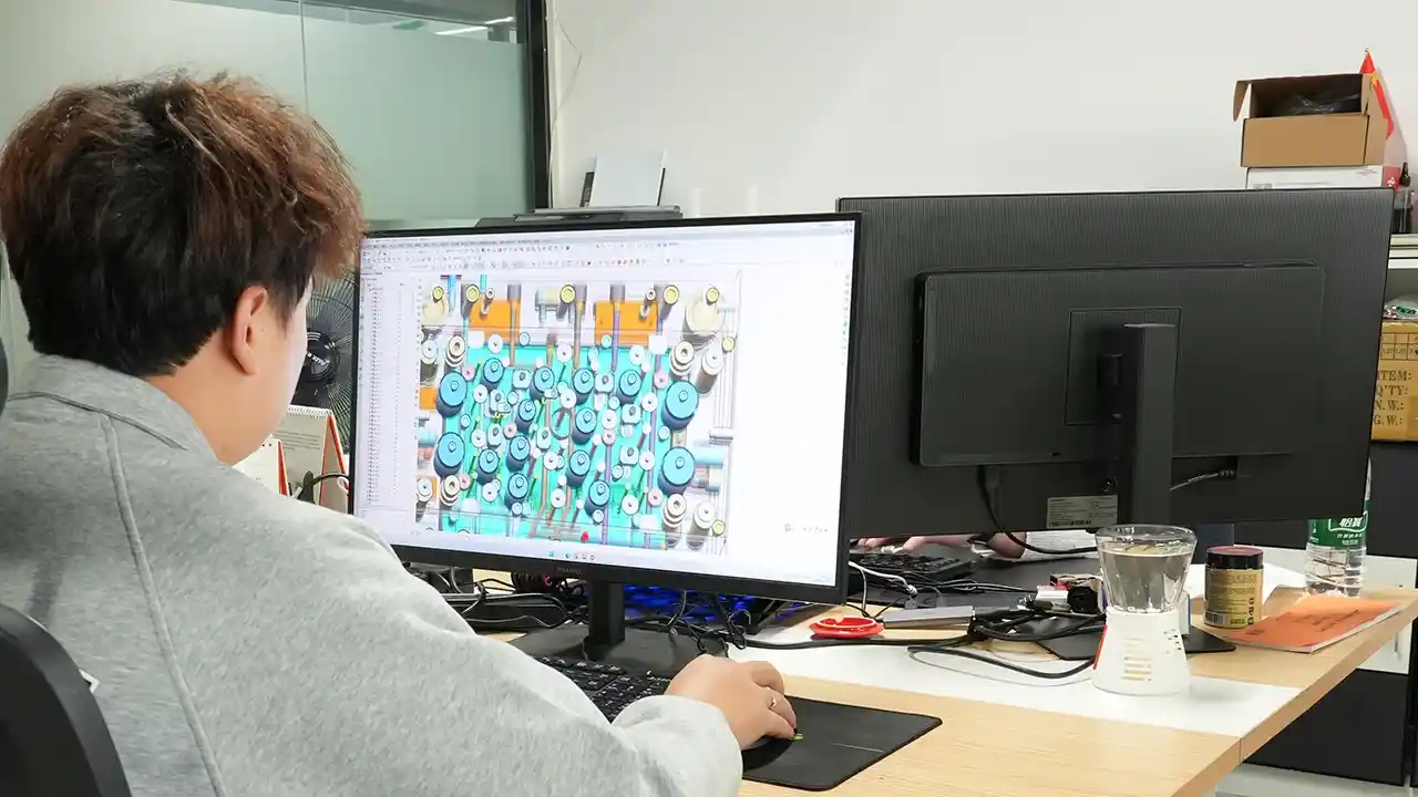
As an FEP plastic fabricator, the Dimud engineering team conducts systematic DFM reviews prior to the launch of every FEP injection molding project to ensure that the material properties are fully aligned with the part design and mold solution.
Core Properties and Specifications of FEP Plastic
Understanding the properties of FEP plastic is essential for making material selection decisions. The following summarizes key parameters from multiple perspectives:
Thermal Performance
| Performance Metrics | Typical values |
|---|---|
| Melting Point (Tm) | 255–265 °C |
| Continuous operating temperature | -200 °C – +200 °C |
| Heat Deflection Temperature (HDT, 0.45 MPa) | 70–75 °C |
| Coefficient of Thermal Expansion (CTE) | 135–170 × 10⁻⁶ /K |
| Thermal conductivity | 0.19–0.25 W/(m·K) |
FEP plastic has a continuous service temperature of up to 200°C, offering a significant advantage over PVDF (150°C). It also exhibits excellent low-temperature performance, maintaining flexibility at temperatures as low as -200°C without becoming brittle or fracturing, making it the material of choice for low-temperature fluid piping and components used in liquid nitrogen equipment.
Mechanical properties
| Performance indicators | Typical value |
|---|---|
| Tensile strength | 20–25 MPa |
| Elongation at break | 250–330% |
| Flexural modulus | 500–700 MPa |
| Hardness (Shore D) | 55–60 |
| Impact Strength (Notched Izod) | No gaps, no cracks |
FEP plastic has a tensile strength significantly lower than that of PVDF, PEEK, or PPS, and its flexural modulus is also lower; it is classified as a “flexible high-performance material” rather than a “rigid structural material.” This characteristic makes it ideal for use in seals, piping assemblies, and thin-walled flexible parts, but it is not suitable for structural components subjected to high loads.
Electrical performance
| Performance indicators | Typical value |
|---|---|
| Dielectric constant (10⁶ Hz) | 2.0–2.1 |
| Dielectric loss (tan δ) | <0.001 |
| Volume resistivity | >10¹⁸ Ω·cm |
| Dielectric strength | 20–24 kV/mm |
FEP plastic has one of the lowest dielectric constants (approximately 2.1) among all thermoplastic polymers. It exhibits extremely low dielectric loss and electrical insulation properties comparable to those of PTFE, making it the standard choice for aerospace-grade cable insulation and high-frequency communication cable jackets.
Other Key Attributes
- Transparency: FEP plastic is a highly transparent material with a visible light transmittance of nearly 96%. It stands out among the family of fluoroplastics and is an ideal choice for applications requiring viewing ports for fluid observation or optical-grade tubing.
- Gas Permeability: FEP plastic has low gas permeability, outperforming PTFE, and is suitable for fluid tubing systems that require gas barrier properties.
- Coefficient of Friction: With a dynamic coefficient of friction of approximately 0.2 and excellent surface non-stick properties, it is suitable for applications requiring protection against scaling and adhesion.
- Moisture Absorption: <0.01%; it absorbs virtually no moisture and does not require pre-drying before injection molding (though clean, dry storage is still recommended).
- Flame Retardancy: UL 94 V-0 rating, LOI (Limiting Oxygen Index) >95%; it is inherently non-flammable and requires no added flame retardants.
FEP Chemical Compatibility: A Detailed Overview
FEP chemical compatibility is one of the key properties that engineers focus on most during the material selection phase. FEP plastic exhibits excellent long-term compatibility with the vast majority of industrial chemicals:
Well-tolerated media
Strong inorganic acids: hydrochloric acid (any concentration), sulfuric acid (<98%), nitric acid (<65%), phosphoric acid, hydrofluoric acid (diluted)—these are off-limits for the vast majority of engineering plastics, but FEP plastic can provide long-term, stable performance in these environments.
Strong oxidizing agents: hydrogen peroxide (below 30%), sodium hypochlorite, ozone, peracetic acid—FEP plastic’s resistance to oxidizing media is the basis for its widespread use in bleaching processes and disinfection systems.
Organic solvents: aliphatic hydrocarbons, aromatic hydrocarbons (benzene, toluene), ketones, esters, alcohols, halogenated hydrocarbons—FEP plastic is essentially immune to these solvents, making it the preferred choice for piping in chemical and pharmaceutical processes.
Alkalis: Sodium hydroxide (any concentration), potassium hydroxide—FEP plastic exhibits significantly greater stability in strong alkaline environments than PVDF, which is one of its key differentiating advantages over PVDF.
Gaseous media: chlorine, fluorine (low concentration), ammonia, sulfur dioxide—FEP plastic’s compatibility with corrosive gases makes it widely used in gas analyzer piping and exhaust gas treatment systems.
Media requiring careful evaluation
FEP plastic’s “nearly universal compatibility” is not absolute. Thorough compatibility testing must be conducted before use in the following situations:
- Fuming sulfuric acid (oleum) and fuming nitric acid: High-concentration, strongly oxidizing acids may cause slight swelling of FEP plastic at high temperatures; operating temperatures and contact duration must be verified.
- Liquid alkali metals (sodium, potassium) and elemental fluorine: These substances break C-F bonds at high temperatures and are among the very few substances incompatible with FEP plastic.
- Certain halogen compounds at extremely high temperatures: Extra caution is required, for example, when hydrogen fluoride and water vapor coexist at temperatures exceeding 200°C.
- High-dose radiation environments: Ionizing radiation can cause molecular chain breakage in FEP plastic, reducing its mechanical properties; in radiation scenarios, the maximum permissible radiation dose should be assessed as a priority.
Practical Recommendations: Before FEP plastic is officially used in contact with corrosive media, it is recommended to conduct immersion tests in accordance with ASTM D543 (Standard Test Method for Chemical Resistance of Plastics), focusing on changes in mass, dimensional changes, and the retention rate of mechanical properties. This step is particularly essential in semiconductor and biopharmaceutical projects.
Advantages and Limitations of FEP Plastic
Advantages
① Near-full-spectrum chemical inertness: FEP plastic exhibits excellent long-term resistance to virtually all industrial chemicals (including strong acids, strong bases, and strong oxidizing agents), and its resistance to alkalis is superior to that of PVDF, making it one of the thermoplastic injection molding materials with the broadest chemical resistance.
② Mass production via injection molding: This is the core engineering advantage of FEP plastic over PTFE—the ability to injection-mold complex-shaped FEP plastic parts in bulk, including thin-walled tubing, valve bodies, connectors, and seals, thereby significantly reducing the unit processing cost.
③ Stability over a wide temperature range: -200°C to +200°C. FEP plastic maintains its structural integrity across the full range of applications, from extremely low to relatively high temperatures, making it one of the few material options suitable for both low-temperature energy storage and high-temperature chemical processing environments.
④ High optical transparency: FEP plastic is the most transparent member of the fluoroplastic family, with a visible light transmittance approaching 96%. It offers unique value in piping, fluid distribution systems, and photochemical reactors where visual monitoring is required.
⑤ Excellent Electrical Insulation Properties: With a dielectric constant of approximately 2.1, extremely low dielectric loss, and a volume resistivity exceeding 10¹⁸ Ω·cm, FEP plastic is the preferred insulating material for high-frequency cables, connector insulation, and precision components in electronic devices.
⑥ Naturally flame-retardant, with an LOI > 95%. FEP plastic meets UL 94 V-0 standards without the need for flame-retardant additives, offering a natural compliance advantage in medical, rail transportation, and aviation electrical systems where safety and compliance requirements are stringent.
⑦ UV-resistant and excellent weather resistance: The C-F backbone of FEP plastic is nearly completely inert to ultraviolet light; it does not yellow, chalk, or crack during long-term outdoor use, making it suitable for outdoor sensor housings, solar cell encapsulation films, and building curtain wall applications.
⑧ Compatible with gamma-ray sterilization: FEP plastic can withstand standard gamma-ray sterilization (within a dose range of 25 kGy) and retains good mechanical properties after sterilization, making it a compliant choice for single-use medical flow systems.
Limitations
① Relatively low mechanical strength; not suitable for structural components. FEP plastic’s tensile strength (20–25 MPa) and flexural modulus (500–700 MPa) are relatively low among high-performance engineering plastics. It cannot withstand significant structural loads and is prone to creep under long-term compression, requiring design margins for structural support.
② The injection molding process window is extremely narrow, making processing difficult. FEP plastic has an extremely low melt viscosity (far lower than that of PVDF or PPS), making it highly prone to “overfill,” flow marks, and flash during injection; simultaneously, high-temperature decomposition releases corrosive gases, placing high demands on equipment materials, and operational errors can be extremely costly. This is the fundamental reason why there are relatively few factories on the market with qualified FEP plastic injection molding capabilities.
③ High cost: The raw material cost of FEP plastic is approximately 10–20 times that of general-purpose engineering plastics; using it in non-essential applications results in significant cost waste.
④ Low surface hardness and limited wear resistance: With a Shore D hardness of approximately 55–60, it lacks sufficient wear resistance in applications involving contact with abrasive particles or high contact stress, making it unsuitable for use as wear-resistant bushings or sliding bearings.
⑤ Low heat deflection temperature (HDT): Although the continuous operating temperature can reach 200°C, FEP’s heat deflection temperature (HDT) under low pressure (0.45 MPa) is only about 70–75°C. This means that its thermal stability under load is far lower than what the continuous operating temperature suggests, requiring special attention in pressurized applications.
⑥ High and Anisotropic Dimensional Shrinkage The linear shrinkage rate of FEP plastic injection-molded parts is approximately 3%–4% (parallel to the flow direction) versus 4%–6% (perpendicular to the flow direction), indicating significant anisotropy. For high-precision dimensional parts, the shrinkage distribution must be predicted through mold flow analysis; otherwise, the first-mold yield rate will be extremely low.
Side-by-Side Comparison of FEP, PTFE, and PFA
When selecting fluoroplastics, FEP, PTFE, and PFA are the three most common candidate materials. Understanding the fundamental differences between them is essential to avoiding selection errors:
| Comparison dimensions | FEP Plastic | PTFE | PFA |
|---|---|---|---|
| Continuous service temperature | ≤200°C | ≤260°C | ≤260°C |
| Tensile strength | 20–25 MPa | 15–35 MPa | 28–33 MPa |
| Chemical resistance | Near full durability (superior to PVDF) | Strongest (near-full endurance) | Near-total chemical resistance (approaching that of PTFE) |
| transparency | Highly transparent | Opaque white | translucent |
| Raw material costs | high | high | Extremely high (approximately 40% higher than FEP) |
| Typical injection molding shrinkage rate | 3–6% | N/A | 2–4% |
Key Selection Criteria:
- When injection molding is required and the budget is more sensitive than with PFA, FEP plastic is the only viable alternative to PTFE for injection molding;
- When the highest chemical resistance is required, along with injection molding or ultra-high-purity semiconductor applications, PFA should be the first choice—it is more expensive but offers superior performance;
- In scenarios where injection molding is not required and only chemical resistance and high-temperature resistance are needed, PTFE formed through machining or sintering is the most cost-effective solution;
- When optically transparent fluoroplastic injection-molded parts are required, FEP plastic is the only mainstream choice.
FEP Plastic Grade System
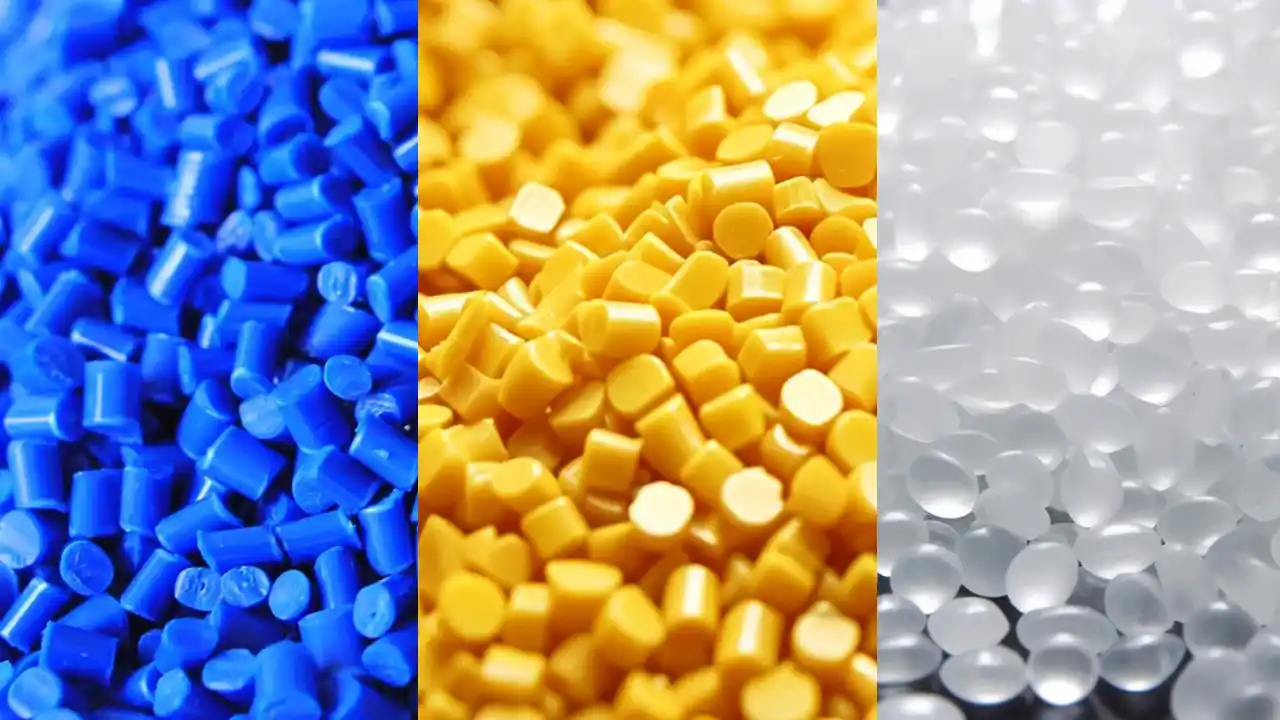
There is more than one grade of FEP plastic material available on the market; they are primarily classified based on melt flow rate (MFR) and intended application:
Injection molding grade and extrusion grade
Injection molding grade FEP (e.g., Teflon® FEP 100, Neoflon® FEP NP-20): Features a higher MFR (approximately 7–12 g/10 min at 372°C) and good melt flowability, making it suitable for injection molding of thin-walled, complex parts; however, the mechanical properties of parts made from this grade are slightly lower than those of high-molecular-weight extrusion grades.
Extrusion-grade FEP (e.g., Teflon® FEP 4100, Neoflon® FEP NP-101): Lower MFR (approximately 1–4 g/10 min), higher melt strength, suitable for the extrusion molding of cable jackets and pipes; not recommended for injection molding (difficult to mold and prone to high residual stress).
Key Principle: When selecting raw materials for FEP injection molding projects, it is essential to specifically request the Technical Data Sheet (TDS) for grades intended for injection molding, as process parameters vary significantly between different grades.
High-Purity Grades
High-purity FEP plastics designed specifically for the semiconductor and biopharmaceutical industries (such as Chemours Teflon® FEP HP-Plus and Daikin Neoflon® FEP for Semiconductor) limit metal ion leaching to extremely low levels (<10 ppb) and must meet SEMI F57 or USP Class VI certification requirements.
Filled and Modified Grades
To address the relatively low mechanical strength of pure FEP plastics, modified FEP grades filled with carbon fiber, glass fiber, or graphite have been introduced to the market. These can increase tensile strength to approximately 55–80 MPa, and the flexural modulus to approximately 3,000–5,000 MPa. However, their chemical resistance and thermal stability may be limited by the chemical compatibility of the fillers, and separate compatibility verification is required when used in corrosive media.
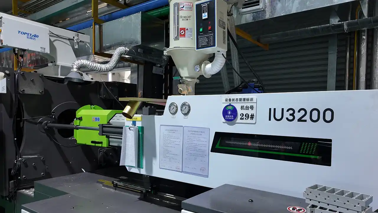
FEP Injection Molding: Key Process Points
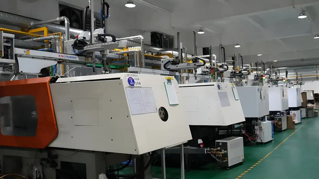
FEP injection molding is one of the most challenging processes in high-performance material injection molding. Below are the key process control points summarized by the Dimud engineering team based on their experience with FEP plastic injection molding projects:
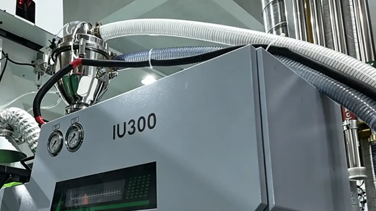
Equipment Requirements
FEP plastic releases corrosive fluorides (such as HF) when it degrades; therefore, all equipment surfaces in contact with the melt must be made of corrosion-resistant materials:
- Barrel and screw: Bimetallic composite barrel (with Ni/Co-based alloy liner); for the screw, Hastelloy C-276 or an equivalent fluorine-resistant material is recommended
- Mold cavities: Corrosion-resistant stainless steel (S316L) is recommended, or PVD/CVD hard, corrosion-resistant coatings (such as DLC or CrN) should be applied
- The use of boron-containing glass fiber (which catalyzes FEP degradation) and MoS₂ lubricants is strictly prohibited.
In addition, the injection molding workshop should be equipped with an adequate ventilation system, and operators must wear fluoride-resistant protective gear when starting up equipment, changing materials, or troubleshooting.
Barrel Temperature Settings
Typical injection molding temperature ranges (Note: The processing temperature for FEP plastic is significantly higher than that for PVDF):
| Zone | Recommended Temperature |
|---|---|
| Feed zone | 260–280 °C |
| Compression zone | 295–310 °C |
| Metering zone | 300–315 °C |
| Nozzle temperature | 295–310 °C |
Important Warning: FEP plastic undergoes severe thermal degradation at temperatures exceeding 380°C, releasing large amounts of corrosive fluorides and toxic gases. The barrel must be equipped with a reliable temperature control system and an over-temperature alarm system; the recommended over-temperature protection setpoint should not exceed 330°C.
Mold Temperature
It is recommended to control the mold temperature between 150–200°C. Higher mold temperatures help to:
- Improve crystallization integrity and enhance chemical resistance
- Reduce residual stress in the part and minimize warpage
- Improve part transparency and surface finish
The high mold temperature requirements for FEP plastic place significant demands on the mold heating system; typically, hot oil circulation heating is required rather than standard water circuits, which is a cost factor that requires special consideration in mold quotations.
Injection Speed and Pressure
FEP plastic has extremely low melt viscosity (far lower than PVDF or PEEK), so injection speed must be strictly controlled:
- Excessively fast injection can cause jetting and flash; the extremely low-viscosity FEP plastic melt has virtually zero tolerance for flash.
- A “slow-fast-slow” staged injection strategy is recommended: slow speed in the gate area (10–15 mm/s), medium speed in the main cavity (20–35 mm/s), and deceleration at the end to prevent gas entrapment
Injection pressure is typically controlled at 50–100 MPa, with holding pressure set at approximately 40%–60% of the injection pressure. The holding time should be relatively short (1–3 s) to avoid flash caused by excessive holding pressure.
FEP Plastic Injection Molding Shrinkage Compensation
FEP plastic has a high and anisotropic shrinkage rate (3%–4% in the flow direction, 4%–6% in the perpendicular direction). For high-precision parts, mold dimensional compensation must be designed only after predicting the shrinkage distribution via Moldflow analysis. The empirical strategy of “uniformly scaling up the shrinkage amount” often fails with FEP plastic, which is the primary reason many factories frequently have to rework molds when undertaking their first FEP injection molding projects.
Shutdown and Cleaning Procedures
Prolonged retention of FEP plastic in the barrel can generate degradation by-products. If downtime exceeds 5 minutes, immediately lower the barrel temperature to below 250°C and maintain low-speed screw rotation; if downtime exceeds 15 minutes, perform a cleaning procedure by flushing residual FEP plastic from the barrel with HDPE or a dedicated cleaning compound to prevent degraded carbonized residues from entering the next production run.
Key Points for Mold Design of FEP Injection-Molded Parts
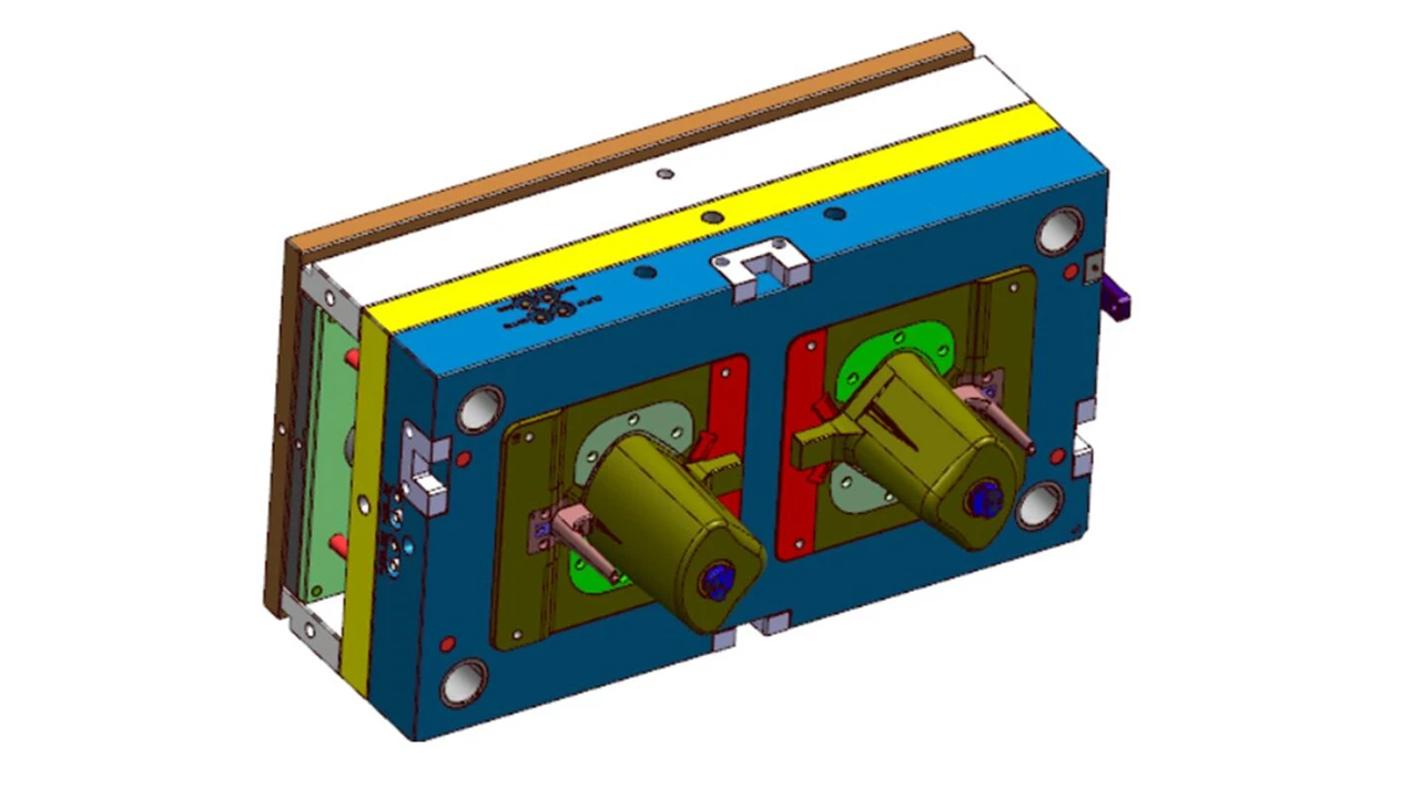
The unique rheological properties of FEP plastic impose different requirements on mold design compared to those of general-purpose plastics. Dimud performs the following DFM checks at the start of every FEP plastic project:
Wall Thickness Design
Recommended wall thickness range: 1.0–3.0 mm. FEP plastic has good melt flowability; ultra-thin walls below 0.5 mm can theoretically be filled, but extremely thin walls significantly amplify shrinkage warpage issues and make venting more difficult. Wall thickness changes should feature smooth transitions (tapered gradients) to avoid abrupt step changes, thereby reducing the risk of warpage caused by uneven shrinkage.
Draft Angle
Since FEP plastic is relatively soft (approximately 55 Shore D), the part itself has some inherent ability to adapt to demolding; however, a minimum draft angle of ≥1° per side (smooth surface) is still recommended. For deep cylinders or deep-hole structures, the draft angle should be increased to 2°–3° per side to prevent drag marks and deformation.
Gate Design
The ultra-low melt viscosity of FEP plastic dictates specific requirements for gate cross-sectional area:
- Gates should not be too small: Small gates cause the melt to further decrease in viscosity under high shear rates (shear thinning effect), leading to uncontrolled flow and the appearance of spatter marks.
- Gates should not be too large: Excessively large gates make it difficult to cleanly remove gate flash, affecting part appearance.
- It is recommended to use side gates (with a gate land depth of 0.5–0.8 mm) or fan gates; avoid using pin gates with excessively small cross-sectional areas.
- The gate should be located at the point of maximum wall thickness and kept away from sealing surfaces and core functional surfaces that come into contact with corrosive media.
8.4 Venting
FEP plastic may generate trace amounts of gas during high-temperature processing. Combined with the melt’s low viscosity and fast filling speed, vent channels must be adequately arranged (depth 0.01–0.015 mm, fully covering the perimeter of the parting line). Otherwise, burn marks are highly likely to occur. Furthermore, the gases generated by FEP plastic degradation are corrosive and can erode the mold steel near areas where venting is insufficient.
Common Injection Molding Defects and Solutions
The following types of defects occur frequently in FEP injection molding:
Flash: FEP plastic has extremely low melt viscosity and is one of the thermoplastic injection molding materials most prone to flash. Remedial measures: Reduce the injection speed and holding pressure; check the alignment accuracy of the parting line (requiring a gap of <0.005 mm); and verify that the clamping force is sufficient.
Discoloration/Degradation Streaks: These are caused by material buildup in dead spots within the barrel or nozzle, or by excessive barrel temperature. Remedial measures: Inspect the nozzle design (to avoid dead spots caused by backflow), strictly follow shutdown cleaning procedures, and lower the temperature in the homogenization zone by 5–10°C to observe any changes.
Warpage: FEP plastic has a high shrinkage rate and is anisotropic; uneven cooling is the primary cause. Remedial Actions: Extend cooling time, improve mold temperature uniformity (maintain the temperature difference between the inlet and outlet within 3°C), and optimize gate location (using mold flow analysis).
Insufficient Transparency: High transparency is a key advantage of FEP plastic; if the part appears milky or cloudy, it is typically due to excessive crystallization caused by too rapid cooling. Remedial Measures: Increase the mold temperature (toward 200°C) and reduce the cooling rate.
Insufficient Weld Line Strength: The chemical durability of the weld line area in FEP plastic is significantly lower than that of the main body when exposed to corrosive media. During the DFM phase, mold flow analysis should be used to position the weld line away from critical functional surfaces and sealing surfaces.
When to Choose FEP Plastic for Injection Molding?
In the following scenarios, FEP plastic is the preferred choice for injection molding:
① Applications requiring contact with strong alkalis: While PVDF has limited resistance to strong alkalis, FEP plastic exhibits excellent long-term stability against strong alkalis (NaOH, KOH) at all concentrations and is suitable for injection molding. This is the clearest application scenario where FEP plastic can replace PVDF.
② Operating temperatures exceed the upper limit of PVDF (>150°C), and injection molding is required. In continuous operating conditions between 150°C and 200°C, PVDF is already approaching its performance limits, whereas FEP plastic has a continuous operating temperature of 200°C, providing a sufficient engineering safety margin.
③ Applications requiring transparent fluoroplastic components for fluid visualization: FEP plastic is the only injection-moldable fluoroplastic capable of providing near-glass-level transparency (light transmittance of approximately 96%), making it the material of choice for transparent chemical piping components, laboratoryware, and fluid monitoring windows.
④ Cryogenic applications (below -100°C). FEP plastic retains its flexibility even at -200°C, making it one of the very few injection-moldable materials suitable for seals and piping components in liquid helium and liquid nitrogen environments.
⑤ Applications requiring gamma sterilization with strict limits on fluoride contamination: FEP plastic withstands gamma sterilization and has extremely low leaching rates, making it a compliant choice for single-use medical fluid delivery systems (such as bioreactors and drug delivery tubing).
⑥ High-frequency electrical insulation applications: For connectors, cable assemblies, or microwave devices requiring extremely low dielectric constants and dielectric loss, FEP plastic offers some of the best electrical performance among all injection-moldable materials.
When Should You Avoid Choosing FEP Plastic?
In the following situations, we recommend abandoning FEP plastic in favor of more suitable alternative materials:
① The manufacturer lacks the capability for fluoroplastic injection molding. FEP plastic places far greater demands on equipment materials, temperature control precision, and operating procedures than general-purpose engineering plastics. Entrusting production to an inexperienced manufacturer results in extremely high scrap rates and significant safety risks. If you are seeking a partner with specialized process capabilities for an FEP plastic project, please contact the Dimud engineering team for a project feasibility assessment.
② Cost-sensitive applications where functionality can be met by PVDF or PPS: If the operating temperature of the part is below 150°C and it comes into contact with strong acids (but not strong alkalis), PVDF offers fully adequate performance and can reduce costs by 50%–70%. You should first evaluate whether PVDF meets your requirements before considering FEP plastic.
③ Structural components requiring high rigidity and strength: The mechanical strength of FEP plastic is relatively low among fluoroplastics, making it completely unsuitable for load-bearing structural components. For high-temperature corrosion scenarios with mechanical performance requirements, PEEK or PPS should be prioritized (their chemical resistance is sufficient for most non-extreme media).
④ Contact with liquid alkali metals or elemental fluorine: In extremely rare cases, liquid sodium or potassium and elemental fluorine gas can attack the C–F bonds in FEP plastic. In such situations, even the maximum performance of PTFE is insufficient; specialty alloy piping should be used instead of any polymer.
⑤ Extremely high dimensional accuracy requirements for parts (tolerance <±0.1 mm). FEP plastic’s anisotropic shrinkage of up to 3%–6% results in extremely high mold debugging costs and very long lead times for high-precision parts. If precision requirements are extremely high, evaluate whether to substitute PFA (which has lower shrinkage and less anisotropy) or switch to a PTFE machining solution.
Applications of FEP Plastic in Major Industries
The unique combination of properties in FEP plastic makes it ideal for high-value applications across all of Dimud’s core service industries:
Medical Device Industry
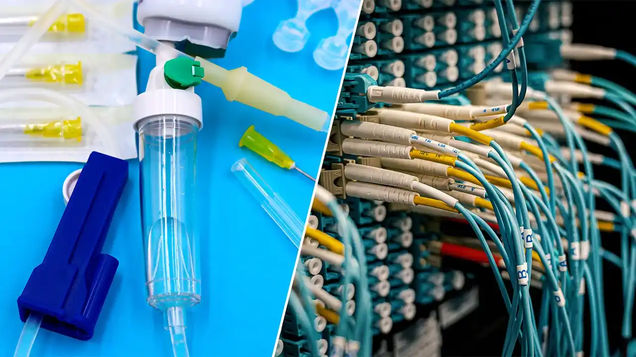
Applications of FEP plastic in the medical field span the following areas:
Catheters and Microfluidic Tubing Assemblies: FEP plastic’s high transparency, biocompatibility, and compatibility with gamma sterilization make it the preferred choice for catheter outer sheaths, microfluidic chip interface tubing, and fluid connectors. Compared to PVC (which contains plasticizers) and silicone (which has limited mechanical strength), FEP plastic offers clear compliance advantages in high-purity fluid delivery systems.
Single-Use Systems: In single-use systems for cell culture, blood processing, and pharmaceutical filling, injection-molded FEP plastic components (valve bodies, connectors, and sampling ports) meet FDA and USP Class VI compliance requirements due to their leach-free, sterilizable, and chemically inert properties.
Pharmaceutical-Grade Contact Parts: FEP plastic is completely inert to solvents commonly used in pharmaceutical processes (isopropyl alcohol, ethanol, ethyl acetate) and contains no plasticizers or stabilizers, making it the preferred material for direct contact with pharmaceutical solutions.
Dimud possesses specialized injection molding capabilities for medical device clients and is well-versed in the production requirements for medical-grade compliant parts. We offer integrated medical device injection molding services ranging from DFM to mass production. We welcome discussions regarding project collaboration.
Consumer Electronics Industry
Although FEP plastic is not as widely used in the consumer electronics sector as ABS or PC, it is irreplaceable in specific high-end applications:
High-frequency connector and cable insulation: With a dielectric constant of approximately 2.1, FEP plastic outperforms most engineering plastics in terms of electrical performance during high-frequency signal transmission in the GHz range and above. It is suitable for insulation sheaths in 5G millimeter-wave modules and high-speed data cables, as well as for connector insulators.
Protective Coatings and Housings for Wearable Devices: FEP plastic’s resistance to sweat, corrosion from cleaning agents, and its non-stick properties make it suitable as an outer protective layer or functional covering for high-end wearable devices (smartwatches, health monitoring patches).
3D-Printed Equipment Components: FEP plastic film is widely used as a release film in stereolithography (SLA) and digital light processing (DLP) 3D printers; its high light transmittance (good UV transmission) and low surface energy (low delamination force) are key performance indicators. Injection-molded FEP plastic hopper frames are also increasingly becoming the preferred choice for professional-grade equipment.
The Current Status of Sustainability and Compliance at FEP Plastic
As global PFAS regulations tighten, FEP plastic procurement teams and product engineers are paying increasing attention to compliance risks. Here are a few key facts:
Current Status of PFAS Classification
From a chemical standpoint, FEP plastic falls under the category of PFAS (per- and polyfluoroalkyl substances) because its molecular chains consist entirely of C-F bonds. However, FEP is a high-molecular-weight perfluorinated polymer that differs fundamentally in behavior from the low-molecular-weight PFAS (such as PFOA, PFOS, and GenX) that have drawn regulatory scrutiny: it is insoluble in water, does not bioaccumulate, and does not migrate from the surface of manufactured parts into the environment.
In its 2024–2025 proposal to restrict PFAS, the European Chemicals Agency (ECHA) has taken the position of “extending the transition period” or granting “exemptions” for high-molecular-weight fluoropolymers (including FEP plastic); however, the proposal is still under review, and a final conclusion has not yet been reached.
Changes in Manufacturing Compliance
The synthesis processes for fluoropolymers have historically involved the use of additives such as PFOA. Major suppliers, including Chemours, Daikin, and Solvay (Syensqo), have fully transitioned to PFOA-free manufacturing processes since 2020; current grades are PFOA-free and comply with the relevant restrictions under the EU’s REACH and POPs regulations. When procuring FEP plastic, it is recommended to explicitly request a PFOA-free declaration and a REACH compliance certificate from suppliers.
Recyclability
FEP plastic is a thermoplastic fluoropolymer that, in principle, can be recycled through melt reprocessing; however, the recycling infrastructure specifically designed for fluoropolymer waste remains underdeveloped in most regions. Sprue and scrap generated during injection molding are typically blended with virgin material at a ratio of less than 20% for reuse, with the impact on part performance remaining within acceptable limits. The primary method of disposal for end-of-life parts is high-temperature incineration (≥1000°C), combined with exhaust gas scrubbing, which breaks down the products into inorganic fluorides.
Frequently Asked Questions
FEP stands for Fluorinated Ethylene Propylene and is a copolymer of tetrafluoroethylene (TFE) and hexafluoropropylene (HFP). It belongs to the class of perfluorinated polymers (perfluorinated thermoplastics) and is one of the few members of the fluoroplastic family that can be processed via melt injection molding and extrusion; it combines the chemical inertness of PTFE with the processing convenience of thermoplastic materials.
There is no absolute superior or inferior option; it depends on the application requirements. PTFE is slightly superior in terms of its range of chemical resistance, maximum heat resistance (260°C), and coefficient of friction (extremely low), but it cannot be processed via melt injection molding—it can only be sintered or machined—making it suitable for simple shapes and small-batch production. FEP plastic sacrifices approximately 60°C of its maximum heat resistance in exchange for melt injection molding capability and high optical transparency, making it suitable for mass-producing complex, precision parts. In short: choose FEP plastic if you need injection molding or transparency; choose PTFE if you need the highest heat resistance or the lowest friction.
Yes. Chemically speaking, FEP plastic contains C-F bonds and falls under the category of PFAS. However, FEP is a high-molecular-weight polymer that is chemically stable, insoluble in water, and does not bioaccumulate; it therefore exhibits fundamentally different environmental behavior compared to strictly regulated short-chain, low-molecular-weight PFAS (such as PFOA and PFOS). Currently, the European Union and the U.S. EPA are in the process of evaluating regulations for high-molecular-weight fluoropolymers. The compliance status of FEP plastic in most applications remains relatively stable at this time, but it is recommended to continue monitoring the latest announcements from ECHA.
EPDM (ethylene propylene diene monomer) is a synthetic rubber elastomer, while FEP plastic is a semi-crystalline perfluorinated thermoplastic; the two are entirely different types of polymers. The key differences are as follows: EPDM offers excellent elasticity (it can recover after significant deformation), as well as good weather resistance and ozone resistance, but its chemical resistance is limited (it is not resistant to strong acids, strong oxidizing agents, or aromatic hydrocarbons); FEP plastic is resistant to virtually all industrial chemicals, but its elasticity is far inferior to that of EPDM, making it more akin to a semi-rigid material. When selecting materials for seals, the two are sometimes in competition: EPDM offers a clear cost advantage in applications involving mild media, whereas FEP plastic or other fluoroplastics must be used in applications involving highly corrosive media.
Under design conditions, the service life of FEP plastic is typically 15–25 years or more. In chemical piping systems, FEP plastic linings and fittings retain their mechanical and chemical integrity even after 20 years of continuous service in strong acidic media; this is the key justification for accepting their high initial cost. The main factors affecting actual service life include: operating temperature (high temperatures accelerate creep and chemical degradation), cyclic stress (fatigue accelerates cracking), exposure to media outside the chemical compatibility range, and the quality of the injection molding process (high residual stress shortens service life).
Yes, FEP plastic exhibits excellent UV stability. The C-F backbone is nearly completely inert to UV radiation; it does not yellow, chalk, or become brittle even after prolonged outdoor exposure, which is in stark contrast to the UV degradation behavior of most organic polymers. It is worth noting that FEP plastic also has very high UV transmittance (approximately 96% visible light transmittance, with similarly high transmittance in the UV spectrum). This allows it to serve both as a UV-resistant material for outdoor protection and as a UV-transmissive window material for photochemical reactors, UV curing equipment, and optical sensors—a unique dual value of FEP plastic in the field of functional materials.
Collaborating with Dimud on an FEP plastic injection molding project.
Dimud is an integrated manufacturer specializing in the development and mass production of high-precision injection molds. With its own mold factory, injection molding plant, and electronics assembly facility, the company has accumulated systematic process expertise in the injection molding of high-performance materials such as PVDF, PEEK, PPS, and LCP, and possesses the engineering capabilities and equipment required to undertake precision injection molding projects involving FEP plastic.
For each high-performance material project, we provide:
- DFM (Design for Manufacturability)
- Analysis (gate design / draft angle / wall thickness uniformity / shrinkage compensation)
- Moldflow Analysis for Shrinkage and Warpage Prediction
- Corrosion-Resistant Mold Material Solutions (S316L / DLC Coating)
- Process Parameter Development and First Article Inspection (FAI)
- Complete Handover from Small-Batch Pilot Production to Mass Production
If you are planning an FEP plastic injection molding project, please feel free to contact us or visit the Dimud Injection Molding Materials Guide to learn about all the high-performance materials we can process.