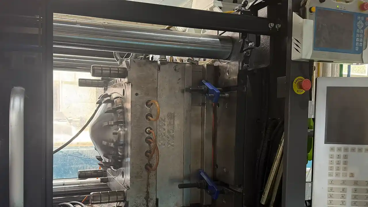

A clean CAD model does not guarantee a successful production launch. In moulage par injection, small design decisions — wall thickness, gate location, cooling layout, parting line placement — can quietly determine whether a tool runs efficiently or becomes an expensive source of defects, delays, and repeated modifications.
De nombreux problèmes liés à l'outillage ne sont pas dus à des erreurs d'usinage. Ils trouvent leur origine bien plus tôt, dès la conception du moule. Lorsque le comportement du matériau, la fabricabilité et les exigences de production ne sont pas pris en compte dès le départ, les équipes sont souvent confrontées à des délais de production plus longs, à une qualité des pièces instable et à des coûts d'outillage qui auraient pu être évités.
La conception de moules à injection est la discipline d'ingénierie qui associe la géométrie du produit, l'architecture de l'outillage, l'écoulement du matériau, les performances de refroidissement et la rentabilité de la production pour aboutir à une solution de fabrication évolutive.
Dans ce guide, nous allons détailler la conception des moules d'injection, les systèmes structurels essentiels à l'intérieur d'un moule, les facteurs qui influencent le coût et la qualité de l'outillage, les erreurs qui font capoter les projets, ainsi que la manière de choisir un partenaire d'outillage qui réduise les risques au lieu de les accroître.
Qu'est-ce que la conception de moules d'injection ?
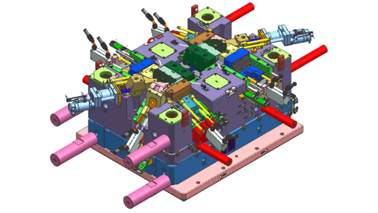
La conception de moules à injection se situe à la croisée de l'ingénierie produit et de la planification des processus de fabrication. La plupart des personnes extérieures au secteur pensent qu'il s'agit simplement d'usiner une empreinte négative de la pièce dans un bloc d'acier. La réalité est bien plus complexe.
La conception de moules d’injection est le processus d’ingénierie consistant à développer l’ensemble du système d’outillage utilisé pour produire des pièces en plastique à grande échelle. Elle définit la géométrie de la cavité et du noyau, l’emplacement de la surface de séparation, le système d’injection et de canaux d’alimentation, la disposition des canaux de refroidissement, la stratégie de dégazage et le mécanisme d’éjection. Chaque décision prise à ce stade détermine directement la précision dimensionnelle de la pièce, la qualité de surface, la durée du cycle, la longévité de l'outillage et le coût de production unitaire. Un moule n'est pas simplement un bloc d'acier façonné : c'est un système thermique et mécanique de précision conçu en fonction de la pièce, du matériau et du contexte de production.
Cette distinction a une importance pratique. De nombreuses équipes produit considèrent la conception du moule comme une étape en aval : elles remettent un fichier CAO finalisé à l’usine et s’attendent à ce que les outilleurs s’occupent du reste. Cette approche aboutit généralement à un moule qui fonctionne techniquement, mais dont les performances ne sont pas optimales. Le placement des points d’injection s’avère fonctionnel, mais pas idéal. Le refroidissement est suffisant mais inefficace. La ligne de joint est fonctionnelle mais visible dans une zone où l’aspect esthétique est important.
Tous ces problèmes auraient pu être évités. La géométrie de la pièce détermine la complexité du moule. Le choix du matériau influe sur la taille des points d’injection et les besoins en refroidissement. Le volume de production détermine s’il est plus rentable d’opter pour un moule à une seule cavité ou à plusieurs cavités. Il ne s’agit pas là de discussions distinctes : elles doivent se dérouler simultanément.
Canal chaud ou canal froid : un choix à faire dès les premières étapes
L’un des premiers choix structurels lors de la conception d’un moule concerne le système de canaux d’injection. Les moules à canaux froids acheminent le plastique fondu à travers des canaux usinés dans les plaques du moule : une solution simple et économique, mais qui génère des déchets (les canaux d’injection) à chaque cycle. Les systèmes à canaux chauds maintiennent le plastique à l'état fondu grâce à un collecteur chauffé, ce qui élimine les déchets liés aux canaux d'injection et réduit les coûts de matière par pièce, mais ils entraînent des coûts d'outillage initiaux importants et une complexité électrique accrue.
Dans le cas d’une production à grand volume utilisant des résines techniques coûteuses, un système à canaux chauds permet généralement d’amortir rapidement son coût grâce aux économies de matière et à la réduction des temps de cycle. Pour les volumes plus faibles ou les programmes soumis à des contraintes budgétaires, le système à canaux froids constitue souvent le choix le plus rationnel. Aucune de ces deux options n’est universellement valable. La décision dépend du volume annuel, du coût des matières premières et de la rentabilité globale du programme — et elle doit être prise dès le début de la conception de l'outillage, et non après.
Moules à deux plaques ou à trois plaques
Un moule à deux plaques constitue la configuration standard : une seule surface de séparation, le canal d’injection restant fixé à la pièce lors de l’éjection. Un moule à trois plaques ajoute un deuxième plan de séparation, ce qui permet de séparer automatiquement le système de canaux d’injection de la pièce lors de l’éjection — ce qui s’avère utile lorsque l’emplacement de la buse d’injection sur la surface de la pièce est limité. Les moules à trois plaques sont plus complexes et plus coûteux à fabriquer et à entretenir. Pour la plupart des applications, un moule à deux plaques doté d’une entrée bien positionnée, en bordure ou en sous-marin, permet d’obtenir le même résultat de manière plus économique.
Comment conçoit-on les moules d'injection ?
Le processus n'est pas aussi linéaire que le laisse entendre un organigramme. Une bonne conception d'outillage repose sur un travail itératif entre le concepteur du produit, l'ingénieur mouliste et, parfois, un spécialiste de la simulation d'écoulement dans les moules. Voici comment cela se déroule généralement dans la pratique.
La conception d'un moule d'injection suit la séquence suivante : examen de la géométrie de la pièce et analyse DFM (Design for Manufacturability, conception en vue de la fabricabilité) → définition de la surface de séparation → disposition des cavités et des noyaux → conception du système d’injection et des canaux d’alimentation → conception des canaux de refroidissement → conception du système d’éjection → sélection de la base du moule → modélisation 3D et plans 2D → simulation du flux de matière → revue finale de la conception et validation de l’outillage. Chaque étape alimente en informations celles qui la précèdent. Une collaboration précoce entre les concepteurs de produit et les ingénieurs mouleurs n’est pas un luxe : c’est ce qui fait la différence entre une fabrication d’outillage sans heurts et une fabrication coûteuse.
Étape 1 : Analyse DFM — C’est là que réside la véritable valeur
Avant de créer la géométrie d'un moule, la conception de la pièce passe par une Analyse DFM. C'est là que s'opèrent les changements les plus utiles — et les moins coûteux.
L'analyse DFM permet de détecter : des angles de dépouille insuffisants qui empêcheront l'éjection propre de la pièce ; des variations d'épaisseur de paroi entraînant un refroidissement différentiel et un gauchissement ; des contre-dépouilles nécessitant des actions latérales ou des élévateurs qui n'ont pas été pris en compte lors de la conception ; des proportions de bossages et de nervures générant des marques d'enfoncement ; et un emplacement des éléments qui place la ligne de joint sur une surface visible d'un point de vue esthétique.
Les problèmes détectés lors de la conception pour la fabrication (DFM) ne coûtent rien à corriger. Modifier le rapport d’épaisseur d’une nervure dans un logiciel de CAO ne prend que vingt minutes à un ingénieur. Ce même changement, une fois le moule fabriqué, nécessite un réusinage de l’insert de cavité, voire le remplacement de l’insert en acier, et entraîne plusieurs semaines de retard. Les chiffres relatifs à la modification des moules sont peu réjouissants : les modifications mineures coûtent généralement entre $2 000 et $8 000 ; les révisions structurelles peuvent atteindre $15 000 à $50 000, voire plus. À aucune étape du processus, l’investissement dans une analyse DFM approfondie n’offre un retour sur investissement aussi faible.
Étape 2 : Modélisation 3D du moule
Une fois que la conception de la pièce est validée comme étant réalisable, l’ingénieur mouliste élabore le modèle solide 3D complet de l’outillage : insert de cavité, insert de noyau, système de canaux d’injection, circuit de refroidissement, disposition des éjecteurs et l’ensemble des composants mécaniques. La conception moderne des moules fait appel à des logiciels de CAO tels que UG NX, CATIA ou SolidWorks. La qualité de ce modèle détermine la précision de l’usinage en aval. Une géométrie ambiguë ou des conflits de tolérances dans le modèle 3D se traduisent par des problèmes sur le plan de la fabrication.
Étape 3 : Simulation du flux de matière dans le moule
Analyse du flux de moulage — à l'aide de plateformes telles que Autodesk Moldflow ou Moldex3D — simule la manière dont le plastique fondu remplit la cavité, refroidit et se solidifie dans les conditions réelles du processus. Il permet de prévoir les défauts potentiels avant même la découpe de l'acier : remplissage insuffisant, poches d'air, emplacement des lignes de soudure, retrait différentiel et déformation de la pièce.
Pour les pièces complexes ou les moules à plusieurs cavités, cette étape est incontournable. Un système de canaux à plusieurs cavités bien équilibré, qui semble correct en CAO, peut néanmoins présenter un déséquilibre de remplissage important lors de la simulation — ce qui entraîne des cavités sous-remplies ou surremplies avec les mêmes paramètres d’injection. Détecter ce problème lors de la simulation coûte quelques jours de travail et le prix d’une licence de simulation. Le détecter une fois le moule en acier coûte une modification du moule et un retard de lancement.
Étape 4 : Outillage et usinage
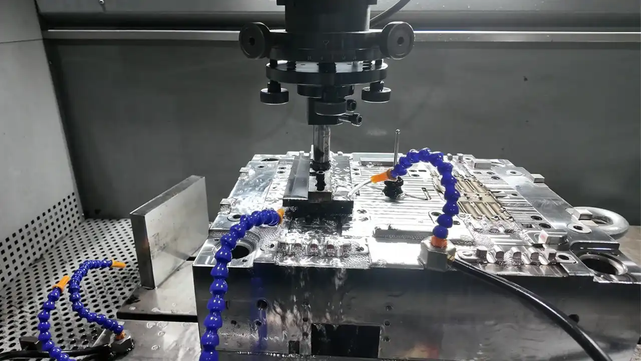
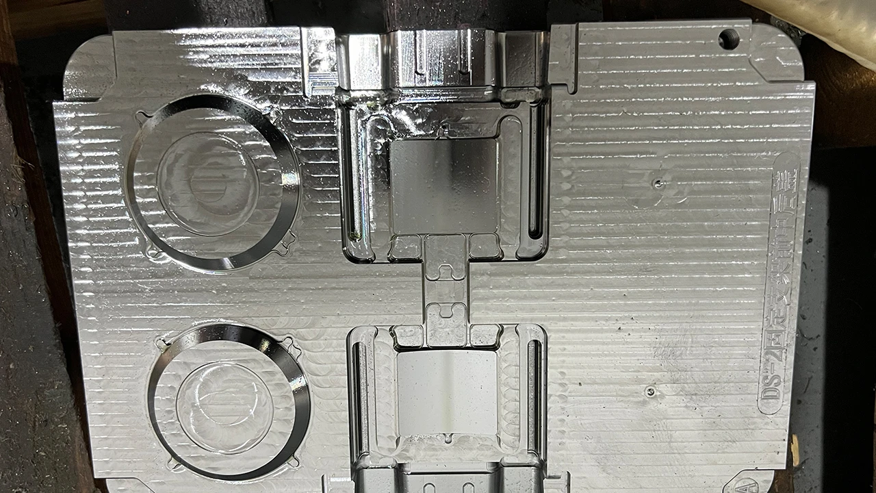
Une fois la conception validée, la base du moule est sélectionnée et l’usinage commence. Les inserts de cavité et de noyau sont généralement usinés en acier : P20 pour les applications standard, H13 pour les volumes élevés ou les matériaux renforcés de verre, et S136 pour les résines corrosives ou les exigences de finition de surface de qualité optique. L'électroérosion (EDM) est utilisée pour les détails fins que le fraisage CNC ne permet pas d'atteindre. Après l'usinage de dégrossissage et de finition, les inserts sont traités thermiquement pour atteindre la dureté souhaitée, puis polis selon les spécifications de finition de surface requises.
La durée totale de fabrication de l'outillage, depuis la validation de la conception jusqu'au premier essai du moule (T1), est généralement de 4 à 6 semaines pour un outillage simple à cavité unique, et de 8 à 12 semaines, voire plus, pour les outillages complexes à cavités multiples ou à tolérances serrées.
Quels sont les éléments structurels essentiels à l'intérieur d'un moule ?
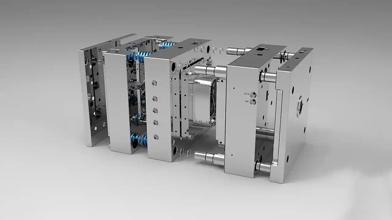
Comprendre ce que contient réellement un moule d'injection aide les équipes produit et les responsables des achats à poser les bonnes questions — et à identifier les problèmes de conception potentiels avant qu'ils ne se transforment en mauvaises surprises coûteuses.
Un moule d'injection se compose de six systèmes fonctionnels qui fonctionnent de concert : la cavité et le noyau (qui définissent la géométrie de la pièce sur toutes ses surfaces) ; le système d'entrée et de canaux d'injection (qui contrôle comment et où le plastique pénètre dans la cavité) ; le système de refroidissement (qui évacue la chaleur et détermine la durée du cycle ainsi que la qualité de la pièce) ; le système d’éjection (qui libère la pièce finie du moule) ; le système de ventilation (qui permet à l’air emprisonné de s’échapper pendant le remplissage) ; et la base structurelle du moule (qui accueille et aligne tous les autres composants). Ces systèmes sont interdépendants : une défaillance dans l’un d’entre eux affecte les performances de tous les autres.
Cavité et noyau
La cavité détermine la surface extérieure de la pièce ; le noyau détermine les surfaces intérieures. Leur tolérance d’alignement, leur état de surface et leur précision dimensionnelle déterminent directement la qualité de la pièce. Pour les pièces de précision — composants médicaux, connecteurs automobiles, éléments optiques —, l’alignement entre la cavité et le noyau est généralement maintenu à ±0,01 mm, voire avec une tolérance plus stricte. La nuance d’acier, le traitement thermique et les spécifications de polissage sont tous définis à ce stade.
Ligne de joint et surface de joint
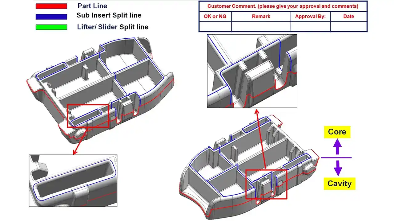
La ligne de joint est le point de jonction entre les deux moitiés du moule. Sa position influe sur l'aspect de la pièce (la ligne apparaît généralement sur la pièce finie sous la forme d'un léger joint), sur le sens d'éjection et sur la complexité globale du moule. Placer la ligne de joint sur un bord non visible, une rupture géométrique naturelle ou une surface tournée à l'opposé de l'utilisateur dans le produit final relève à la fois d'un choix esthétique et d'une décision technique — un choix qui doit être pris par une personne maîtrisant ces deux aspects du problème.
Canaux de refroidissement
Le refroidissement représente généralement entre 60 et 70% de la durée totale du cycle de moulage par injection. Des circuits de refroidissement mal conçus entraînent une répartition inégale de la température au niveau de la cavité et du noyau, ce qui provoque un gauchissement, des variations dimensionnelles d'une injection à l'autre et des cycles inutilement longs. Refroidissement conforme — lorsque les canaux de refroidissement épousent les contours de la pièce plutôt que de suivre des lignes droites percées — cela peut considérablement améliorer l'uniformité thermique pour les géométries complexes. Cette technique entraîne toutefois une augmentation des coûts et une plus grande complexité d'usinage, c'est pourquoi elle est réservée aux applications où la durée du cycle ou les exigences de qualité justifient cet investissement.
Conception de portails
La buse d’injection est le point d’entrée par lequel le plastique fondu s’écoule dans la cavité. Son emplacement, ses dimensions et son type déterminent l’équilibre du flux, la position de la ligne de soudure, l’aspect des traces de buse sur la pièce finie, ainsi que le risque de dégradation du matériau due au cisaillement au niveau de la buse. Pour les pièces soumises à des exigences esthétiques, le placement de l'entrée de matière est souvent l'un des premiers points abordés lors de la revue de conception — car déplacer une entrée de matière une fois le moule construit implique de modifier le canal d'injection et, éventuellement, l'acier de la cavité. Un aperçu complet de les types de portes logiques et leurs compromis Il convient d'examiner ce point avant de prendre une décision définitive concernant l'emplacement des portails.
Système d'éjection
Les broches d'éjection, les manchons, les lames et les plaques de démoulage laissent chacun des marques différentes sur différentes surfaces de la pièce. Ces marques sont inévitables ; la question est de savoir où elles se situent. L'emplacement des broches d'éjection doit être coordonné avec la conception de la pièce afin de garantir que les marques apparaissent sur des surfaces non esthétiques ou sur des surfaces qui seront masquées lors de l'assemblage. Il s'agit là d'un autre domaine dans lequel la conception du produit et l'ingénierie des moules doivent faire l'objet d'une communication précoce. Un concepteur de produit qui ne sait pas où seront placés les éjecteurs ne peut pas prendre de décisions éclairées concernant les spécifications de finition de surface.
Quels sont les facteurs à prendre en compte lors de la conception d'un moule d'injection ?
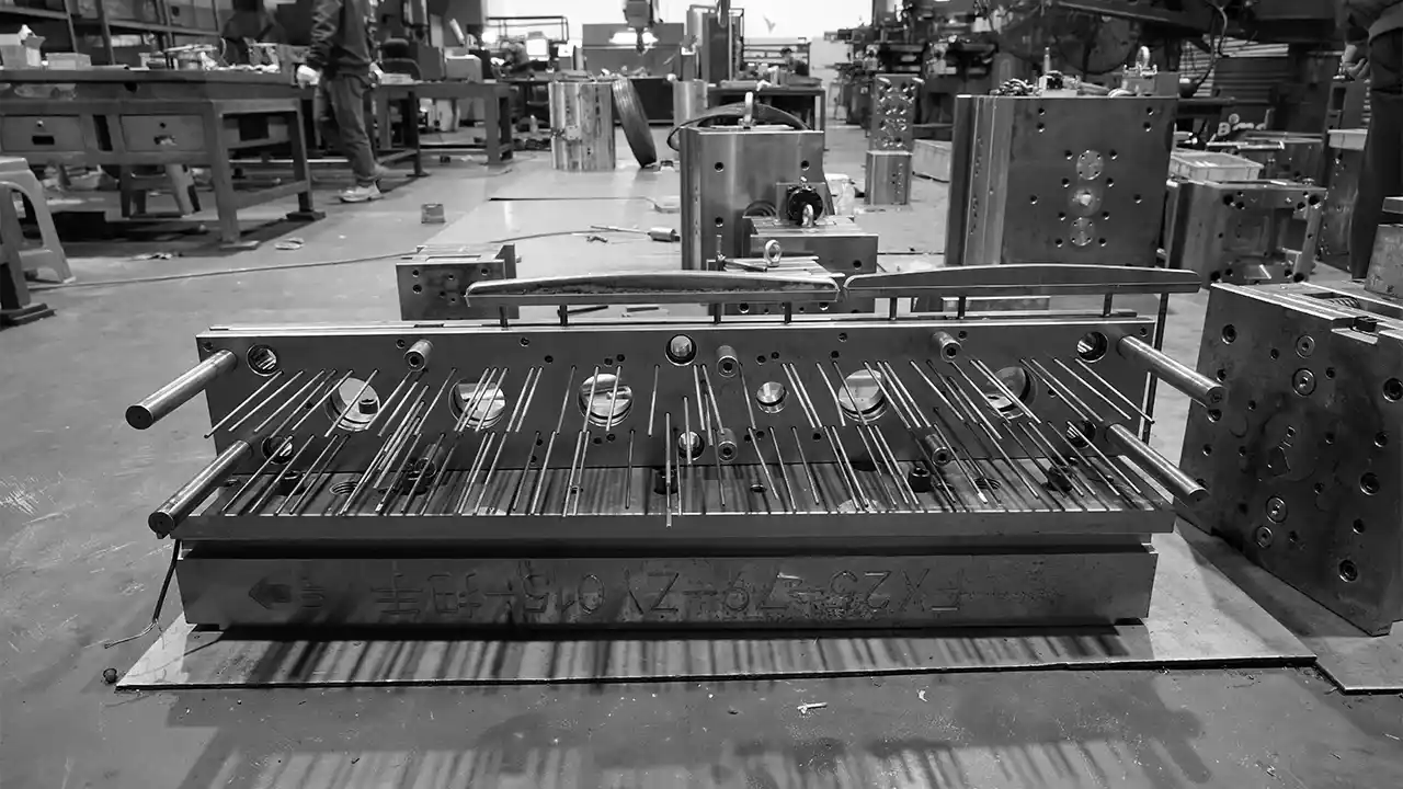
C'est là que les ingénieurs expérimentés se distinguent. Les variables sont nombreuses et interagissent entre elles : en modifier une a des répercussions simultanées sur plusieurs autres.
Les facteurs clés dans la conception d’un moule d’injection comprennent : la géométrie et la complexité de la pièce (contre-dépouilles, parois minces, nervures profondes, exigences en matière de finition de surface) ; le choix du matériau (taux de retrait, viscosité, température de transformation, abrasivité) ; les tolérances dimensionnelles requises ; le volume de production et la durée de vie visée du moule ; le nombre de cavités ; les exigences en matière de temps de cycle ; et le budget alloué à l’outillage. Aucun facteur ne peut être optimisé isolément. Chaque décision implique des compromis entre le coût, la qualité et la facilité de fabrication — et ces compromis doivent être faits en toute connaissance de cause, par des personnes qui en maîtrisent tous les aspects.
Le choix des matériaux détermine pratiquement tout ce qui vient ensuite
Les différents plastiques se comportent de manière très différente à l'intérieur d'un moule, et les spécifications du matériau doivent être définies avant le début de la conception du moule — et non après. Le polypropylène présente un taux de retrait volumétrique d’environ 1,5 à 2,51 TP3T ; le PEEK ne se rétracte que de 0,1 à 0,51 TP3T. Une cavité de moule dimensionnée pour l’un ne peut pas produire des pièces aux dimensions précises pour l’autre sans modifications.
La viscosité détermine les dimensions de l'entrée et les exigences en matière de pression d'injection. La température de transformation influe sur les dimensions et l'emplacement des canaux de refroidissement. Les matériaux chargés de fibres (nylon chargé de verre, PEEK chargé de carbone) sont abrasifs : ils accélèrent l’usure des surfaces de la cavité et nécessitent des nuances d’acier à outils plus résistantes. Les matériaux transparents comme le PC ou le PMMA exigent des cavités polies miroir, sans traces d’usinage qui pourraient transparaître à travers la pièce. Le bon assistance technique en matière de conception de moules Cela signifie que ces contraintes liées aux matériaux sont intégrées dès le départ dans l'outillage, et ne sont pas découvertes qu'après la réalisation des premiers échantillons (T1).
Épaisseur et uniformité des parois
L'uniformité de l'épaisseur des parois est l'un des principes de conception les plus fondamentaux dans l'ingénierie des pièces en plastique — et l'un de ceux qui sont le plus souvent bafoués lorsque les concepteurs de produits n'ont pas travaillé en étroite collaboration avec les ingénieurs outilleurs. Les sections épaisses refroidissent plus lentement que les sections minces. Ce refroidissement différentiel génère des contraintes internes, lesquelles provoquent un gauchissement et des variations dimensionnelles après l'éjection.
En règle générale, pour la plupart des matériaux, il est recommandé de maintenir une épaisseur de paroi comprise entre 1,5 mm et 4 mm, avec des transitions progressives plutôt que des sauts brusques. Il s'agit toutefois d'une recommandation générale : l'épaisseur de paroi appropriée dépend du matériau spécifique, de la géométrie de la pièce, des exigences structurelles et des paramètres de fabrication. Un support structurel automobile en nylon chargé de verre ne présente pas les mêmes exigences en matière d'épaisseur de paroi qu'un boîtier esthétique d'appareil électronique grand public en ABS.
Angles de repérage
L'angle de dépouille est la pente appliquée aux surfaces parallèles à la direction d'ouverture du moule. Sans dépouille suffisante, la pièce adhère au moule lors de l'éjection, ce qui peut entraîner des traces de frottement, des dommages à la surface ou des pièces coincées. À titre indicatif, une dépouille de 1° pour 25 mm de profondeur d'éjection constitue un point de départ valable pour la plupart des surfaces lisses. Les surfaces texturées nécessitent un angle de dépouille nettement plus important — généralement entre 3° et 5° au minimum, en fonction de la profondeur de la texture — car la texture s'accroche mécaniquement à la paroi de la cavité.
C'est un domaine où les concepteurs de produits et les ingénieurs mouleurs sont souvent en désaccord. Les concepteurs souhaitent un dévers minimal afin de préserver la géométrie prévue. Les ingénieurs mouleurs ont besoin d'un dévers suffisant pour garantir une éjection fiable. La bonne solution se situe presque toujours entre les deux, et s'obtient par le dialogue plutôt que par l'imposition d'une partie à l'autre.
Exigences en matière de tolérance
Toutes les pièces n'exigent pas le même niveau de précision dimensionnelle. Les composants de dispositifs médicaux peuvent nécessiter des tolérances de ±0,02 à 0,05 mm. Les boîtiers de produits grand public peuvent être parfaitement fonctionnels avec des tolérances de ±0,15 à 0,2 mm. Plus les exigences de tolérance sont strictes, plus le moule doit être conçu avec précision, plus l’acier à outils doit être résistant et plus le processus doit être contrôlé avec soin. Spécifier des tolérances plus strictes que ce dont la pièce a réellement besoin est une erreur courante et coûteuse : cela fait grimper le coût de l’outillage, allonge le temps de fabrication et peut rendre la pièce plus difficile à fabriquer qu’elle ne devrait l’être.
Quelles sont les erreurs les plus courantes dans la conception des moules d'injection ?
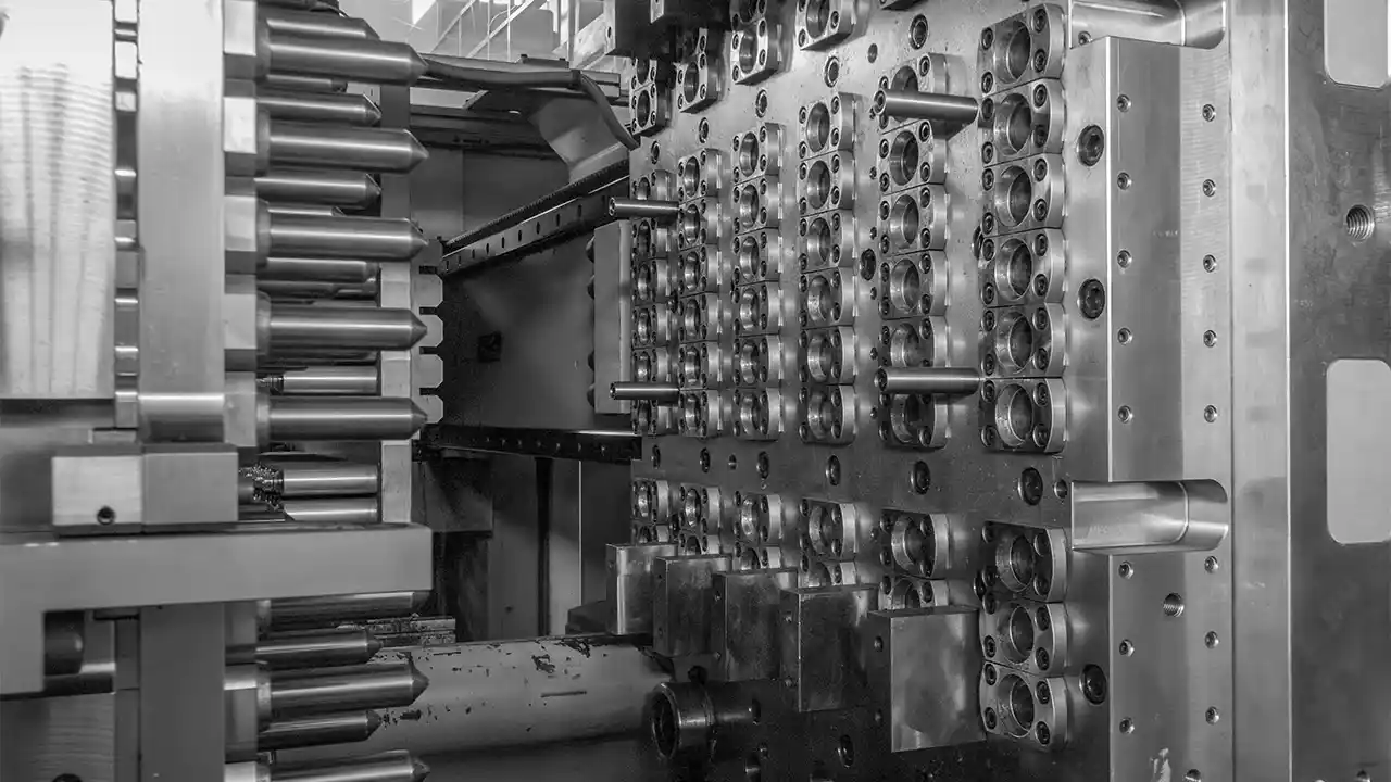
Dans le domaine de l'outillage, l'expérience est le maître le plus coûteux. La plupart des retards et des dépassements de budget dans les projets trouvent leur origine dans un petit nombre d'erreurs récurrentes.
Parmi les erreurs les plus fréquentes dans la conception des moules d’injection, on peut citer : des angles de dépouille insuffisants entraînant une résistance à l’éjection et des dommages à la surface ; la non-prise en compte du retrait du matériau lors du dimensionnement de la cavité ; un refroidissement inadéquat ou déséquilibré entraînant un gauchissement et des temps de cycle prolongés ; un emplacement des points d’injection qui place les lignes de soudure dans des zones critiques sur le plan structurel ; des variations d’épaisseur de paroi générant des marques d’affaissement ; et des contre-dépouilles découvertes tardivement dans le processus — une fois l’outillage fabriqué — nécessitant des ajouts coûteux de mécanismes à action latérale ou des révisions de conception. La plupart de ces problèmes ont une cause commune : la conception du produit et l’ingénierie du moule ont été traitées comme des phases distinctes et séquentielles plutôt que comme un processus unique et intégré.
Contre-dépouilles
On parle de « contre-dépouille » de toute caractéristique de la pièce qui empêche l’éjection dans le sens principal d’ouverture du moule. Les trous latéraux, les crochets à encliquetage, les logos en creux, les ouvertures latérales : tous nécessitent soit une modification de la conception, soit une action latérale mécanique dans le moule (un composant coulissant qui se déplace perpendiculairement à l’axe d’ouverture principal avant l’éjection). Les actions latérales augmentent les coûts, la complexité et le risque de désalignement et de bavures. Tout cela ne pose aucun problème si ces éléments sont identifiés dès la phase de conception pour la fabrication (DFM) et intégrés dès le départ dans l’outillage. Si elle est découverte après la fabrication du moule, une action latérale imprévue peut coûter entre $5 000 et $15 000 à mettre en œuvre, sans compter le retard occasionné par la modification.
Ignorer la simulation Mold Flow
Il est tentant de faire l’impasse sur l’analyse de l’écoulement dans le moule pour gagner du temps au début du projet. Et parfois, pour des pièces simples à cavité unique fabriquées dans des matériaux bien connus, des ingénieurs en moulage expérimentés peuvent concevoir un moule fonctionnel sans y recourir. Mais pour les moules à cavités multiples, les géométries complexes ou les matériaux présentant un comportement d’écoulement difficile, faire l’impasse sur la simulation s’avère être une fausse économie. Lorsqu’un essai T1 révèle un moulage insuffisant d’un côté d’un moule à 4 cavités, ou une ligne de soudure traversant un bossage porteur, le coût du diagnostic et de la correction sur l’acier dépasse largement ce qu’aurait coûté une simulation.
Considérer le « Design Lock » comme le coup d'envoi de la production
Les équipes produit qui finalisent leur conception puis la transmettent à un mouliste sans examen technique ont tendance à obtenir des outils qui fonctionnent — mais pas de manière optimale. L’entrée de matière est placée là où c’était possible, et non là où c’était idéal. Le circuit de refroidissement suit un tracé pratique, et non celui qui serait le plus efficace. La ligne de joint se situe là où la géométrie le permettait, et non là où l’esthétique ou la fonctionnalité l’auraient exigé. Il s’agit là de résultats sous-optimaux qui deviennent des caractéristiques permanentes de chaque pièce produite par ce moule. Le processus de création d'outils donne les meilleurs résultats lorsque l'ingénierie produit et l'ingénierie de fabrication sont coordonnées avant que les décisions ne soient définitivement arrêtées.
Combien coûte la fabrication d'un moule d'injection ?

Tout le monde veut un chiffre. En réalité, cela dépend — mais voici un cadre qui reflète la répartition réelle des coûts.
Le coût d'un moule d'injection varie généralement entre $3 000 et $10 000 pour les moules prototypes simples à cavité unique, et entre $25 000 et $150 000+ pour les moules de production complexes à cavités multiples. Les principaux facteurs de coût sont les suivants : la taille et la complexité géométrique de la pièce, le nombre de cavités, les tolérances dimensionnelles requises, la nuance et la dureté de l’acier du moule, les exigences en matière de finition de surface, le nombre d’actions latérales ou de poussoirs, ainsi que le choix d’un système à canaux chauds ou froids. Les outillages fabriqués en Chine coûtent généralement entre 40 et 70% de moins que des outillages équivalents fabriqués aux États-Unis ou en Europe occidentale — sans pour autant sacrifier la qualité lorsque le bon partenaire est sélectionné.
À quoi ressemblent réellement les chiffres ?
Un moule à cavité unique, de géométrie simple, en acier P20 — sans contre-dépouilles, avec des tolérances standard de l’ordre de ±0,1 mm, un canal froid et une surface texturée — pourrait coûter entre $5 000 et $9 000 chez un outilleur chinois compétent. Ajoutez deux actions latérales pour les ouvertures latérales, une cavité polie miroir pour une résine transparente, et resserrez les tolérances à ±0,05 mm : ce même moule à cavité unique coûte désormais entre $18 000 et $28 000.
Le coût des moules à plusieurs cavités varie considérablement. Un moule à canaux chauds équilibrés à 4 cavités destiné à un connecteur automobile, avec des exigences de tolérance de ±0,03 mm, pourrait coûter, de manière réaliste, entre $60 000 et $120 000. Le rapport coût/pièce à grande échelle justifie cet investissement — le coût initial est bien réel et doit être budgétisé avec précision.
Outillage de prototypage vs outillage de production
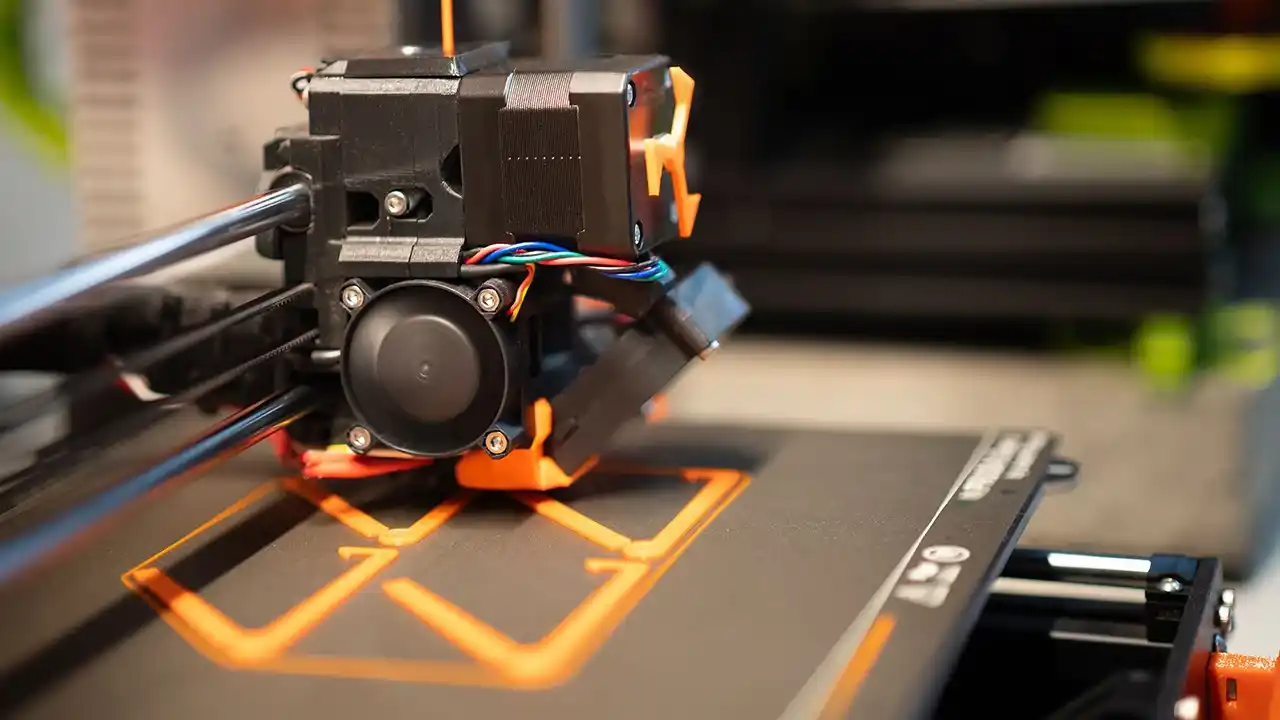
Outillage de prototypage (outillage souple ou outillage rapide) utilise de l’aluminium ou de l’acier de qualité moyenne et est conçu pour un nombre limité de moulages — généralement entre 1 000 et 10 000. Le délai de fabrication est de 2 à 3 semaines, le coût est de 30 à 50% par outillage de production, et cette solution est véritablement utile pour valider la conception des pièces et le processus avant de s’engager dans un investissement de production à grande échelle. Le compromis : la stabilité dimensionnelle et la qualité de surface sont inférieures à celles des outillages en acier trempé, et l’outillage ne permettra pas de supporter des volumes de production soutenus.
Outillage de production Il utilise de l’acier trempé — H13 pour les applications exigeantes, S136 pour les environnements corrosifs ou les exigences de qualité optique — et est conçu pour une durée de vie comprise entre 500 000 et plus d’un million de coups, à condition d’être correctement entretenu. Le délai de fabrication est de 4 à 8 semaines pour une complexité standard. Il s’agit de l’infrastructure idéale pour tout programme présentant des volumes de production significatifs, et la différence de coût par rapport à un outillage prototype devient moins importante lorsqu’elle est amortie sur le nombre total de moulages.
Choisir un outillage de prototypage pour un produit dont la production atteindra plus de 50 000 unités par an sous prétexte que cela revient moins cher au départ constitue une erreur de planification, et non une économie.
Le poste que personne ne prévoit dans son budget : la modification des moules
Le poste le plus souvent négligé dans les budgets consacrés à l’outillage est celui des coûts de modification. D’après l’expérience du secteur, 30 à 50% des moules nécessitent au moins une modification avant d’atteindre une production stable — qu’il s’agisse d’ajuster la taille d’une entrée de matière, d’ajouter un système d’évacuation des gaz, de corriger un écart dimensionnel ou de retravailler un circuit de refroidissement qui ne fonctionne pas comme prévu. Les modifications mineures coûtent entre $2 000 et $8 000 et prennent entre 1 et 2 semaines. Les modifications structurelles impliquant le remplacement d’inserts coûtent entre $10 000 et $40 000 et prennent entre 3 et 6 semaines. Prévoir une marge de sécurité de 15 à 20% du budget initial d’outillage pour les modifications n’est pas du pessimisme, mais une planification rigoureuse.
Comment choisir le bon partenaire pour la conception de moules ?

Le partenaire avec lequel vous travaillez influence le résultat autant que la conception elle-même. Choisir un fabricant d'outils en se basant principalement sur le prix proposé est l'un des moyens les plus sûrs de se retrouver confronté à des problèmes coûteux.
Lors de l'évaluation des partenaires chargés de la conception et de la fabrication de moules par injection, les facteurs les plus importants sont les suivants : les capacités internes en matière de conception pour la fabrication (DFM) et d'ingénierie des moules (au-delà de la simple exécution de l'usinage) ; les compétences en matière de simulation de flux de moulage ; la précision d’usinage et la capacité à respecter une tolérance de ±0,01 mm, voire meilleure, sur les cotes critiques ; la qualité et la traçabilité de l’approvisionnement en acier ; la qualité de la communication pendant la fabrication de l’outillage ; et une expérience avérée avec des pièces présentant une complexité similaire et répondant aux exigences du secteur. Le devis le moins cher et le meilleur résultat proviennent rarement de la même source.
Un aspect qui est systématiquement sous-estimé lors de la sélection d'un fournisseur est le niveau d'expertise technique. Une usine qui usine des moules selon vos plans propose une offre très différente de celle d'un partenaire technique qui examine votre conception avant même de tracer la moindre ligne de la géométrie de l'outil, signale les problèmes qui vous coûteront de l'argent par la suite, effectue une simulation de flux dans le moule pour valider la conception, puis fabrique l'outil avec des paramètres validés par le processus.
La deuxième option implique un investissement initial plus élevé. Elle s'avère toutefois globalement moins coûteuse, si l'on tient compte des modifications évitées, d'un délai plus court avant d'atteindre une production stable et d'une réduction des rebuts lors des premières séries de production.
Chez Dimud, notre approche en matière de fabrication de moules de précision réunit en une seule opération l’analyse DFM, la simulation de l’écoulement dans le moule et l’usinage de précision de l’acier — plus de 30 ingénieurs chevronnés, dont la plupart possèdent plus de 20 ans d’expérience pratique dans l’outillage plastique. Sur plus de 1 000 projets analysés dans le cadre du DFM, le constat le plus récurrent n’est pas que les conceptions soient erronées. C’est qu’elles comportent 3 à 5 problèmes corrigibles que personne n’avait signalés — car l’équipe produit et l’équipe moules n’avaient pas encore eu de véritable échange technique.
Conclusion
C’est lors de la conception du moule d’injection que se déterminent la fabricabilité, la qualité et la rentabilité à long terme d’un produit — et non pas dans l’atelier de production, ni après que les premiers échantillons (T1) se sont révélés défectueux. Chaque décision prise lors de la phase de conception du moule a des répercussions sur chaque moulage réalisé par celui-ci pendant toute la durée de vie du programme. C’est le fait de définir correctement l’emplacement de la ligne de joint, la disposition des canaux de refroidissement, le positionnement des points d’injection, les angles de dépouille et les dimensions des cavités adaptées au matériau avant même que l’acier ne soit découpé qui fait la différence entre les lancements qui se déroulent sans encombre et ceux qui rencontrent des difficultés. Considérez la conception des moules comme une discipline d’ingénierie, faites appel dès le début à l’expertise appropriée, et la plupart des mauvaises surprises coûteuses ne se produiront tout simplement pas.