If you’re sourcing complex, high-precision metal components at scale — whether for automotive sensors, surgical instruments, firearm components, or consumer electronics — you’ve likely encountered the term metal injection molding and wondered whether it’s the right process for your project.
This guide draws on our team’s direct experience supporting product development projects across automotive, medical, electronics, and robotics sectors. We’ll walk you through exactly how the process works, when it makes economic sense, what materials you can use, and how to evaluate whether an MIM supplier is truly equipped to deliver consistent quality at production volumes.
While Dimud’s core expertise lies in plastic injection molding services and precision mold manufacturing, we regularly collaborate with engineers and procurement teams who are evaluating MIM alongside plastic and die-cast alternatives. This guide is written to help you make that decision clearly.
What Is Metal Injection Molding?
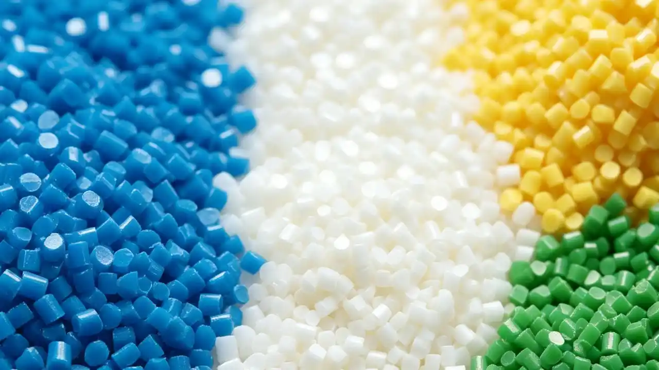
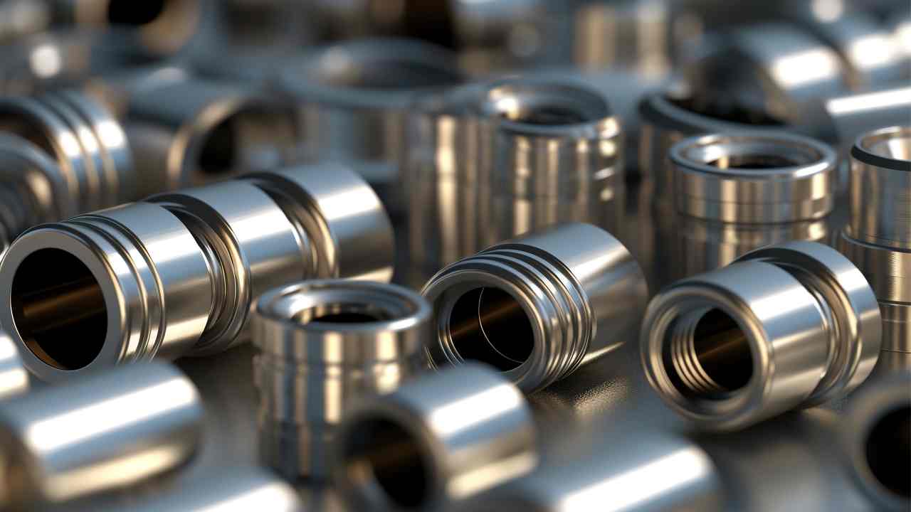
Metal Injection Molding (MIM) is a net-shape manufacturing process that produces small, geometrically complex metal components in high volumes. It bridges two established technologies — powder metallurgy and plastic injection molding — by combining fine metal powders with a thermoplastic binder to create a moldable feedstock that can be shaped using conventional injection molding equipment.
The finished parts exhibit near-full metal density, mechanical properties comparable to wrought or machined metals, and surface finishes that typically require no further processing. This combination of design freedom, material performance, and production scalability makes MIM particularly valuable in industries where miniaturization, complexity, and reliability all converge.
The technology originated in the late 1970s and has matured significantly over the past four decades. Today, MIM components are found in everything from orthodontic brackets and laparoscopic instrument tips to transmission parts and smartphone camera modules.
How the MIM Process Works: Step by Step
The MIM process consists of four primary stages. Each stage involves critical process parameters that directly influence final part quality. Understanding these steps helps you anticipate design constraints and have more productive conversations with your manufacturing partner.
Stage 1: Feedstock Preparation
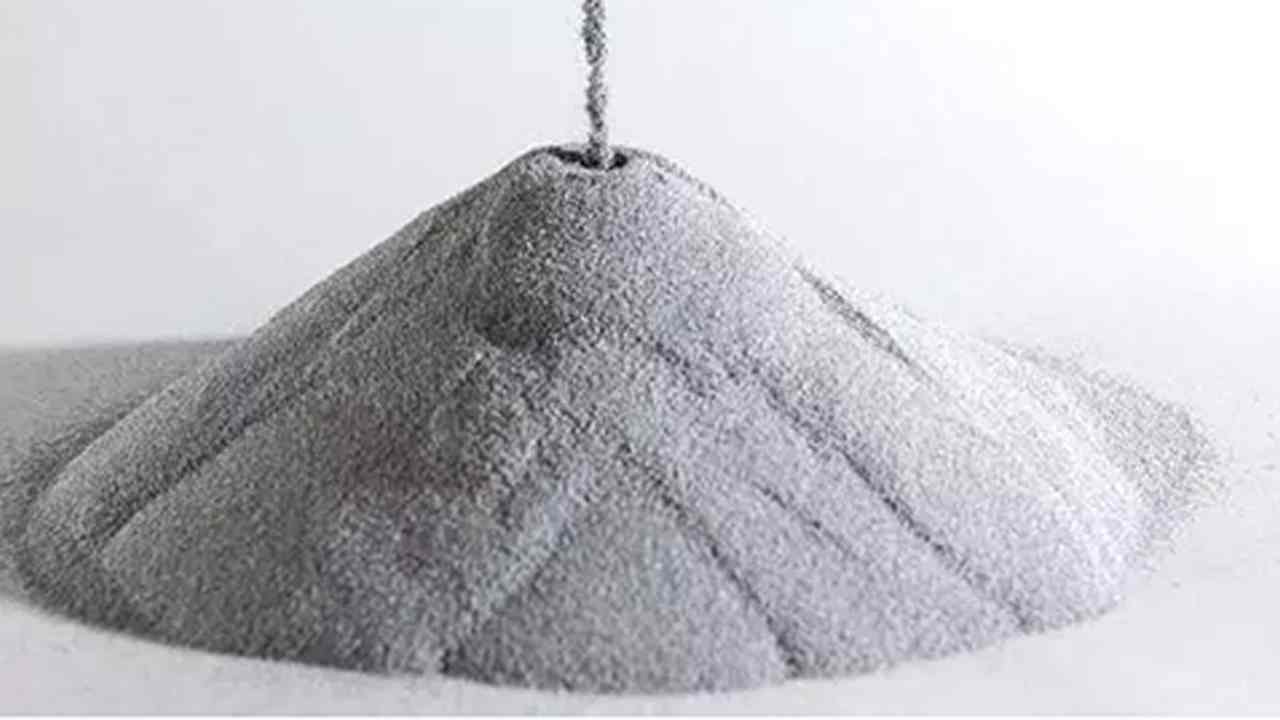
The process begins with selecting metal powder of the appropriate alloy chemistry and particle size — typically under 20 micrometers in diameter, though specialty applications may use finer powders in the 5–10 µm range for improved sintered density. Finer powders provide better surface finish and density after sintering, but they also increase raw material cost and require more careful handling.
This metal powder is then compounded with a multi-component binder system — typically a mix of waxes, polyethylene, and backbone polymers — using high-shear mixing equipment. The resulting compound is granulated into feedstock pellets that behave like a thermoplastic during injection but contain 55–65% metal by volume.
Feedstock formulation is one area where supplier capability and experience matter enormously. Inconsistent powder-to-binder ratios lead to density variations in the final part — a defect that’s almost impossible to detect visually but will compromise mechanical performance.
Stage 2: Injection Molding (Green Part)
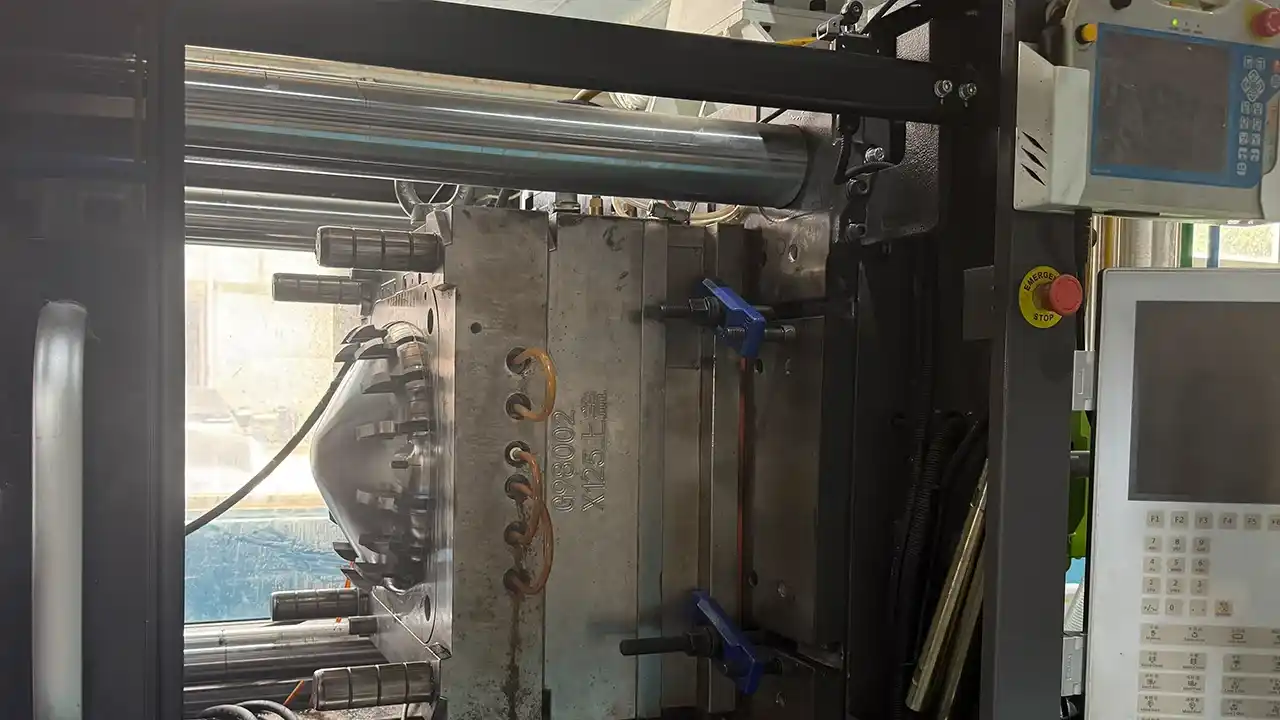
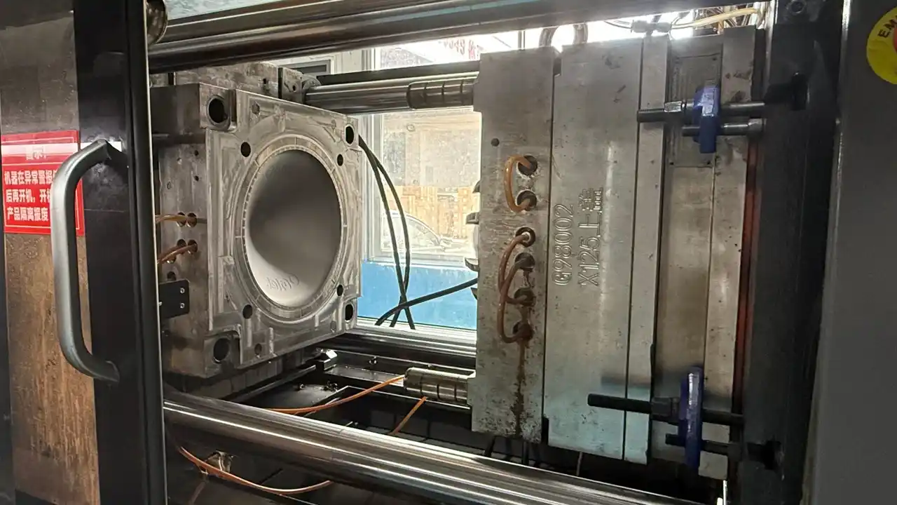
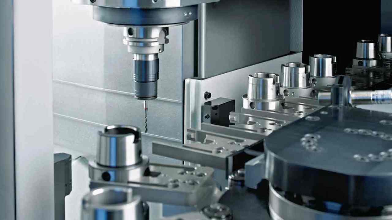
The feedstock is fed into a standard reciprocating screw injection molding machine and injected into a precision steel mold under controlled temperature and pressure. At this stage the process looks identical to plastic injection molding, and shares many of the same equipment and tooling principles.
The resulting “green part” holds its shape but contains approximately 35–40% binder by volume. It’s fragile compared to the final metal component and must be handled carefully through the subsequent stages.
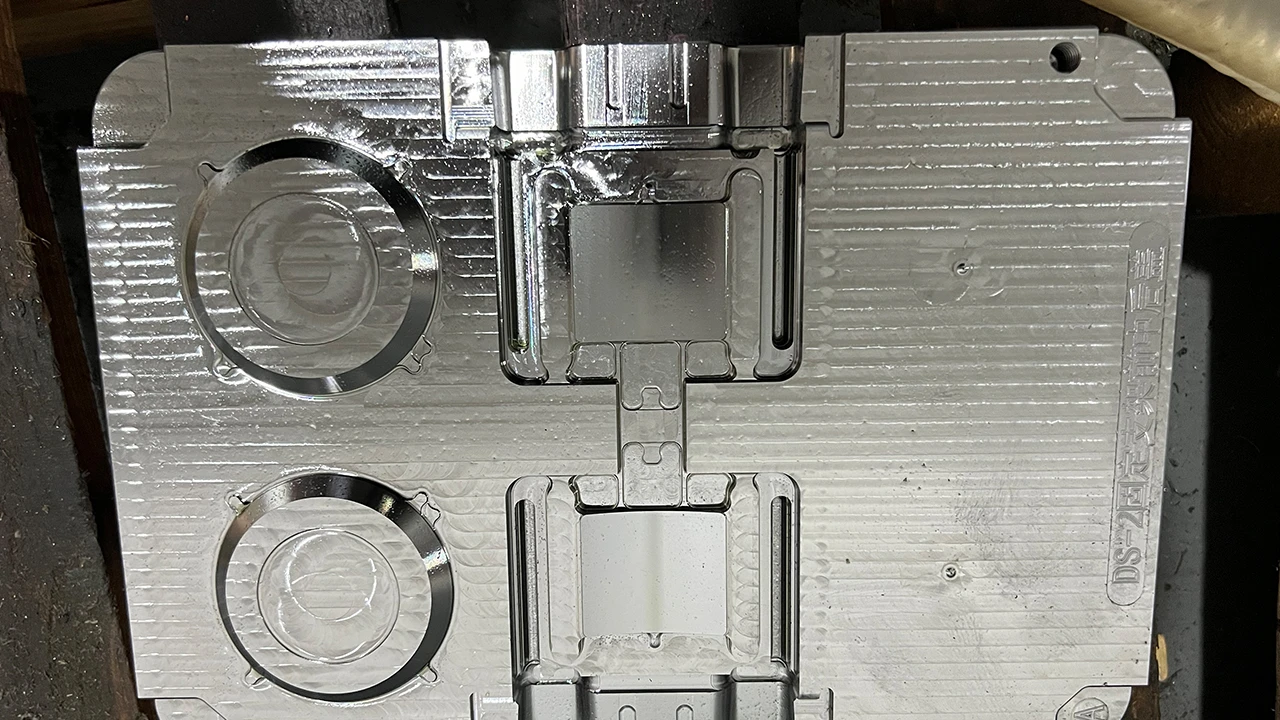
MIM tooling is designed following similar principles to plastic injection molds, including gate location, runner systems, draft angles, and venting — though the higher viscosity of metal feedstock and the need for precise shrinkage compensation require specific expertise. Mold design for MIM parts must account for linear shrinkage of approximately 15–20% that occurs during sintering, which means every critical dimension must be engineered into the tool geometry with this factor in mind. Suppliers who also have deep expertise in injection mold manufacturing bring transferable engineering discipline to this stage.
Stage 3: Debinding
Debinding removes the binder from the green part without disturbing the powder skeleton. There are three main debinding methods in industrial use:
Solvent debinding: The green part is immersed in a solvent that dissolves the primary binder component while leaving the backbone polymer intact. This is the most widely used industrial approach and works well for stainless steel, low-alloy steels, and iron-nickel alloys.
Catalytic debinding: The part is exposed to a gaseous acid atmosphere (typically nitric acid) that depolymerizes the binder from the outside in. This method is faster and more controllable than solvent debinding and is particularly common in high-volume automotive and medical MIM production in Europe and Japan.
Thermal debinding: The part is placed in a furnace at sub-sintering temperatures where the binder burns or evaporates. This is often used as a secondary step after solvent debinding to remove residual backbone polymer. Thermal debinding alone, without a prior solvent or catalytic step, carries a higher risk of part distortion and carbon contamination.
After debinding, the part is referred to as a “brown part” — it still holds its shape through the remaining powder skeleton but is highly porous and extremely fragile.
Stage 4: Sintering
The brown part is loaded into a continuous or batch furnace with a precisely controlled atmosphere (typically hydrogen, nitrogen, or vacuum) and heated to 70–85% of the metal’s melting point. At this temperature, the metal powder particles bond through solid-state diffusion, eliminating porosity and densifying the part to 95–99%+ of theoretical density.
The sintering process also produces the shrinkage mentioned earlier. Well-designed MIM tooling and well-characterized feedstock result in highly predictable and repeatable shrinkage, enabling tight dimensional control across production runs.
Sintered parts may undergo additional secondary operations including:
- CNC machining for critical features requiring tighter tolerances than sintering can achieve (CNC milling or CNC turning)
- Heat treatment for hardness, case depth, or stress relief
- Surface finishing such as electropolishing, plating, or passivation
- Straightening for thin-walled parts that may distort during sintering
MIM Materials: Metals, Alloys, and Selection Criteria
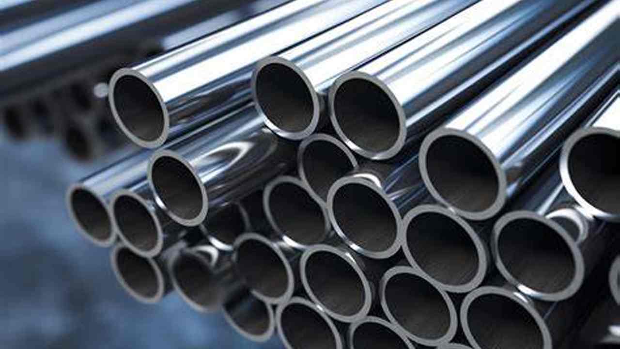
One of MIM’s most significant advantages over die casting is its material range. Because the process involves solid-state powder metallurgy rather than liquid-metal casting, it can process metals with melting points far too high for conventional die casting, including stainless steels, titanium alloys, and nickel-based superalloys.
Stainless Steels
The most widely used MIM materials are austenitic and precipitation-hardened stainless steels:
316L stainlesssteel offers steel offers excellent corrosion resistance and biocompatibility. It’s the material of choice for medical devices, food processing components, and marine applications. Its relatively low strength compared to martensitic grades is compensated by its superior corrosion performance in aggressive environments.
17-4PH (17-4 Precipitation Hardening) combines good corrosion resistance with high strength after age hardening — yield strengths of 900–1,100 MPa are achievable in the H900 or H1025 condition. This makes it one of the most versatile MIM materials for structural components in aerospace, firearms, and industrial equipment.
420 stainless steel is a martensitic grade used where hardness and wear resistance are priorities, including cutting tools, surgical blades, and valve components.
Low-Alloy and Tool Steels
4140 and 4605 steels deliver high strength and toughness at a lower cost than stainless grades. They’re used extensively in automotive powertrain components, power tools, and firearms.
M2 and M42 tool steels are used for wear-resistant components like cutting inserts and forming tools. MIM enables complex internal geometries in these materials that would be prohibitively expensive to machine.
Titanium Alloys
Ti-6Al-4V (Grade 5 titanium) is the gold standard for biomedical implants due to its exceptional combination of strength, low density, biocompatibility, and corrosion resistance. MIM of titanium requires vacuum sintering and specialized powder handling to prevent oxygen contamination, which makes it more technically demanding and expensive. For implant-grade components, the process must comply with ASTM F2885 and ISO 22068 standards.
Nickel Alloys and Tungsten
Inconel 625 and 718 are processed by MIM for aerospace and high-temperature applications where oxidation resistance and elevated-temperature strength are required.
Tungsten heavy alloys are used for radiation shielding, counterweights, and kinetic energy penetrators, where MIM’s ability to produce near-net-shape parts from this otherwise very difficult-to-machine metal provides a significant cost advantage.
Material Selection Considerations
When working with an engineering partner early in your project — as part of a Design for Manufacturability (DFM) review — these factors should guide material selection:
- Mechanical requirements: tensile strength, yield strength, elongation, hardness, fatigue life
- Corrosion environment: Saline, acidic, alkaline, or oxidizing conditions
- Temperature range: Both operating and any sterilization or cleaning cycles
- Regulatory requirements: FDA, EU MDR, RoHS, REACH compliance where applicable
- Cost sensitivity: Stainless steels are most economical; titanium and nickel alloys significantly increase feedstock cost
MIM vs. Alternative Manufacturing Processes
Understanding where MIM fits in the manufacturing landscape requires honest comparison with the alternatives your team is likely considering.
MIM vs. CNC Machining
CNC machining offers the best dimensional accuracy and the widest material choice. For low-volume production of simple geometries, it’s often the right answer. However, machining complex internal geometries — undercuts, blind cross-holes, internal threads, thin walls — dramatically increases cycle time and cost. MIM becomes economical when part geometry is complex and volumes exceed approximately 10,000–20,000 units per year. Our CNC machining services are frequently used for secondary operations on parts whose primary structure is produced by a near-net-shape process.
MIM vs. Investment Casting
Investment casting (lost-wax casting) also produces complex near-net-shape metal parts and handles larger part weights than MIM. However, investment casting generally cannot match MIM’s dimensional accuracy, minimum wall thickness, or internal feature capability. MIM’s typical part weight ceiling is around 100–200 grams; investment casting handles heavier components but with lower dimensional precision and rougher as-cast surfaces.
MIM vs. Die Casting
Die casting offers high production rates at low per-part cost for aluminum, zinc, and magnesium alloys. If your part doesn’t require steel-level strength or the specific properties of stainless steel or titanium, die casting may be more economical at very high volumes. But die casting is limited to lower-melting-point alloys and cannot match MIM’s geometric complexity or dimensional tolerance capability. Our die casting mold expertise allows us to support clients evaluating both processes.
MIM vs. Additive Manufacturing (Metal 3D Printing)
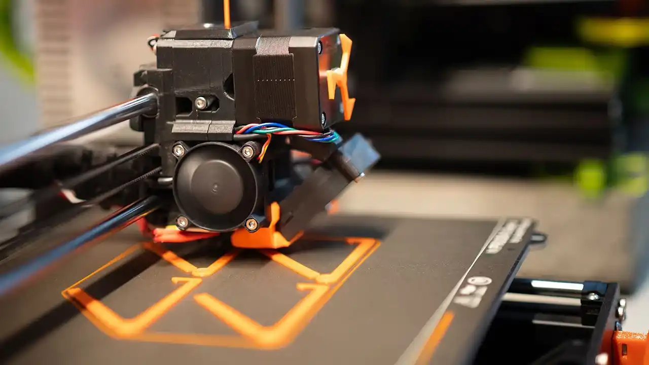
Metal additive manufacturing is appropriate for prototype quantities, highly customized one-off parts, or geometries with internal lattice structures that no other process can produce. For production volumes above a few hundred parts per year, MIM’s per-part cost is typically far lower, and its mechanical properties more consistent. Additive manufacturing should be viewed as a prototyping tool rather than a production alternative to MIM in most cases.
Process Selection Summary
| Factor | MIM | CNC Machining | Investment Casting | Die Casting |
|---|---|---|---|---|
| Geometric complexity | Very High | Medium | High | Medium |
| Minimum wall thickness | ~0.3 mm | ~0.5 mm | ~1.5 mm | ~0.8 mm |
| Dimensional tolerance | ±0.3–0.5% | ±0.005 mm | ±0.5–1% | ±0.1–0.3% |
| Economic volume threshold | 10k+ units/year | 1–1000 units | 500–50k units | 50k+ units |
| Material range | Very broad | Broadest | Broad | Al, Zn, Mg |
| Part weight range | <100–200g | Unlimited | 1g–100 kg | 1g–50 kg |
Dimensional Capabilities and Tolerances
MIM’s dimensional accuracy is defined by two factors: the precision of the injection mold and the repeatability of the sintering shrinkage. Well-controlled MIM processes achieve:
- Dimensional tolerance: ±0.3–0.5% of nominal dimension as-sintered (±0.1–0.2% possible with CNC secondary operations)
- Surface roughness: Ra 1.6–3.2 µm as-sintered, improvable to Ra 0.4 µm or better with post-process polishing or electropolishing
- Minimum wall thickness: 0.3–0.5 mm for most alloys, with thinner walls possible in some titanium and stainless steel applications
- Minimum feature size: Internal holes down to 0.5 mm diameter; external radii down to 0.1 mm
- Part weight range: Typically 0.1 g to 200 g, with most economical applications in the 1–50 g range
For features where tighter tolerances are required — precision bores, mating surfaces, threaded features — secondary CNC operations are routinely applied after sintering. A well-integrated supplier should be able to manage this as part of a single-source solution, as it’s directly analogous to the assembly and secondary processing coordination we provide within our own manufacturing ecosystem.
Industries and Applications Where MIM Excels
Automotive Industry
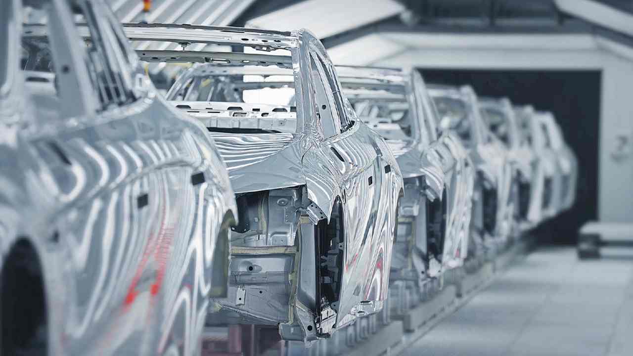
MIM has become a standard production process for numerous precision automotive components, particularly where mass reduction, geometric complexity, or high-volume cost efficiency are priorities. Typical automotive MIM applications include:
- Turbocharger vanes and nozzle rings
- Fuel injector components and seats
- Lock mechanism hardware
- Sensor housings and brackets
- Transmission shift forks and pawls
The automotive sector’s strict dimensional and mechanical requirements align well with MIM’s capability profile. Our experience with automotive parts manufacturing — including structural parts, interior systems, and electronic housings — gives us insight into the quality standards and production consistency automotive OEMs and Tier 1 suppliers demand.
Medical and Dental
The medical industry was among the earliest adopters of MIM, driven by the need for complex, miniaturized surgical instruments and implant components in biocompatible materials:
- Laparoscopic instrument jaws and forceps
- Orthodontic brackets and buccal tubes
- Bone screws and plate systems (titanium MIM)
- Endoscope components
- Drug delivery device mechanisms
Medical MIM requires full traceability, validated processes, and compliance with applicable standards (ISO 13485, ASTM F2885 for titanium, and FDA 21 CFR Part 820). Our medical device manufacturing capability in plastic injection molding has given our team direct familiarity with the documentation and process control expectations of this sector.
Consumer Electronics and Semiconductor
The consumer electronics industry drives significant MIM volume, particularly in smartphones, wearables, and professional audio equipment. Applications include:
- Smartphone hinge mechanisms and SIM card trays
- Camera module lens actuator housings
- Smartwatch crown and button mechanisms
- Laptop hinge components
The demand for miniaturization, surface finish quality, and production volumes in the hundreds of millions of units annually makes MIM uniquely positioned in this space. Our electronics and semiconductor manufacturing experience, including enclosures, connectors, and thermal management components, provides relevant context for evaluating MIM in this context.
Robotics and Energy Storage
Emerging sectors including industrial robotics, collaborative robots (cobots), and battery systems for electric vehicles are creating new demand for MIM components:
- Actuator housings and joint components for robotic arms
- Precision gear and gear segment components
- Battery module fasteners and thermal interface hardware
The shift toward electrification and automation is accelerating development cycles in these sectors, placing a premium on prototyping speed and the ability to scale quickly — themes central to our approach in robotics and energy storage manufacturing.
Firearms and Defense
MIM became widespread in the firearms industry during the 1990s as manufacturers sought to reduce machining costs on trigger group components. Today, a significant proportion of commercial and defense small arms use MIM components for:
- Trigger and sear components
- Safety levers and selectors
- Hammer and firing pin parts
- Bolt catch and release mechanisms
The combination of 4140 or 17-4PH stainless-steel properties with complex three-dimensional geometries that would require multiple machining setups makes MIM particularly compelling in this sector.
Design Guidelines for MIM Parts
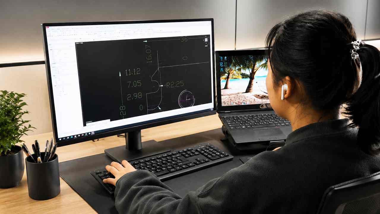
Optimizing your design for MIM before tooling begins is critical. As with plastic injection molding, design decisions made after tooling is cut are expensive to reverse. A thorough DFM analysis at the design stage — covering wall thickness, draft angles, gate location, and shrinkage compensation — can eliminate the most common causes of part failure and tooling rework.
Wall Thickness
- Nominal wall thickness: 1.0–6.0 mm is ideal for most MIM applications. Walls thinner than 0.5 mm require careful process design; thicker walls (>8 mm) significantly increase debinding time and risk of cracking.
- Uniform walls are preferred. Large variations in cross-section create differential shrinkage during sintering, leading to distortion or internal stress.
- Avoid sharp transitions. Where thick and thin sections meet, use tapers or fillets to facilitate uniform powder flow and reduce sintering stress.
Gate and Runner Design
Gate location significantly affects surface quality (a gate mark will remain on the sintered part unless removed by machining) and fill pattern. Work with your mold designer to position gates away from critical functional surfaces and to enable balanced fill across multi-cavity tools.
Draft Angles
Similar to plastic injection molding, MIM parts require draft angles on vertical walls to facilitate part ejection. A minimum of 0.5° is typically required; 1–2° is preferred.
Holes, Slots, and Internal Features
MIM can produce through-holes down to 0.5 mm in diameter. Blind holes present more challenges during debinding and sintering due to trapped binder. Slots and thin ribs down to 0.3 mm are achievable. Complex internal passages that would be impossible to machine can often be designed directly into the mold.
Sintering Support and Distortion
Parts with large unsupported overhangs or asymmetric mass distribution may distort under gravity during sintering. Work with your supplier to design appropriate sintering supports or orient parts to minimize distortion. This is a manufacturing process engineering challenge — the kind of upstream engagement that separates suppliers with genuine engineering design and mold engineering depth from commodity toolmakers.
Design Consolidation
One of MIM’s most powerful economic benefits is part consolidation — replacing a multi-piece machined assembly with a single MIM component. This reduces assembly cost, eliminates tolerance stack-up, and often improves reliability. Challenge your design team to evaluate whether features currently produced as separate parts can be integrated.
Common MIM Defects and How to Prevent Them
Understanding the root causes of MIM defects helps you ask the right questions when qualifying suppliers and reviewing first-article inspection results.
Dimensional variation beyond tolerance: Usually caused by inconsistent feedstock mixing (powder-to-binder ratio), variable sintering temperature profiles, or inadequate mold shrinkage compensation. Requires to be characterized, validated feedstock and tightly controlled furnace cycles.
Warping and distortion: Results from non-uniform wall thickness, poorly designed sintering supports, or rapid heating rates during sintering. Address through DFM at the design stage and validated sintering profiles.
Cracks and delamination: Often caused by aggressive debinding (too high a temperature rise rate in thermal debinding or incorrect solvent choice) or by residual binder at the surface-to-core boundary. Well-controlled debinding parameters and feedstock characterization prevent this.
Surface porosity: A few surface pores is normal in MIM. Excessive porosity indicates insufficient sintering temperature or time, or feedstock contamination. Sintered density should be verified by Archimedes method during process validation.
Short shots and incomplete fill: Caused by insufficient injection pressure, premature freezing of thin walls, or inadequate venting. Addressed through mold design optimization and process parameter development.
Carbon contamination: Particularly relevant for titanium MIM. Binder burnout under inadequate vacuum or with incorrect atmosphere leaves residual carbon that embrittles the sintered part. Requires rigorous atmosphere control and process characterization.
A capable MIM supplier will have documented process control procedures, incoming material inspection (IQC), in-process quality control (IPQC), and final inspection (FQC) — the same quality framework applied across all manufacturing processes at facilities with serious quality and certification commitments.
Cost Factors: When MIM Is Economical — and When It Isn't

MIM’s cost structure differs fundamentally from machining or casting. Understanding this structure helps you evaluate quotes and identify opportunities for cost reduction.
Tooling Cost
MIM tooling is similar in construction and cost to plastic injection molds — multi-cavity, precision steel tooling with careful gating and cooling. Depending on part complexity and number of cavities, tooling cost typically ranges from $8,000 to $80,000 or more for complex, multi-cavity tools. This upfront cost must be amortized over the production volume, which is why MIM economics improve significantly at higher volumes.
Feedstock Cost
Metal powders are significantly more expensive than plastic resins. Stainless steel and low-alloy steel feedstock costs are manageable; titanium and nickel superalloy feedstocks can multiply raw material cost by 10–30× compared to standard grades. For cost-sensitive applications, material selection is one of the most impactful decisions you can make.
Sintering Furnace Cost
Sintering requires high-temperature vacuum or controlled-atmosphere furnaces that are capital-intensive. For batch furnaces, furnace utilization directly affects unit economics. High-volume programs benefit from continuous sintering furnaces that dramatically reduce per-part energy cost.
Break-Even Volume
As a general guide, MIM becomes economically competitive with CNC machining for geometrically complex parts at annual volumes above approximately 10,000–20,000 units. Below this threshold, CNC prototyping or rapid tooling in aluminum may offer better economics. Above 100,000 units per year, MIM’s per-part cost advantage over machining is typically substantial.
Cost Reduction Strategies
- Design consolidation: Replacing two or three machined parts with one MIM component eliminates assembly labor and tolerance stack-up
- Multi-cavity tooling: Tooling investment increases modestly, but per-part cost drops proportionally
- Material substitution: In some applications, 17-4PH or 316L can replace more exotic alloys with minimal performance compromise
- Secondary operation reduction: Design features directly into the mold where possible rather than relying on post-sinter CNC operations
How to Evaluate an MIM Supplier

Selecting an MIM supplier is a consequential decision that affects your product quality, delivery reliability, and ability to scale. Based on our experience managing supply chain and supplier qualification across hundreds of production projects, here are the most important evaluation criteria:
Technical Capability Depth
Ask potential suppliers to demonstrate their experience with your specific alloy and part geometry. Request case studies of similar components. A supplier with genuine MIM expertise will be able to discuss feedstock characterization, sintering profile development, and dimensional control methodology — not just lead times and pricing.
DFM and Engineering Support
Does the supplier have in-house mold design and engineering staff who will provide Design for Manufacturability feedback before tooling begins? Early engineering engagement is the single most important factor in avoiding costly tooling changes and first-article failures. This is analogous to the DFM and mold engineering front-end we provide for every project, regardless of the manufacturing process involved.
Quality System
Look for ISO 9001 certification as a baseline. For automotive applications, IATF 16949 compliance demonstrates the level of process control and documentation discipline required for Tier 1 supply. For medical applications, ISO 13485 certification is the appropriate benchmark. Request copies of relevant certificates and check their validity.
Materials Traceability
For aerospace, medical, and defense applications, full material traceability from powder batch to finished part is non-negotiable. Ask how the supplier documents feedstock lot, green part batch, and sintering furnace run for each production lot.
Secondary Operations Capability
Can the supplier manage CNC machining, heat treatment, and surface finishing in-house or through a closely managed supply network? Single-source responsibility for all post-sinter operations reduces coordination risk and simplifies incoming inspection at your facility.
Capacity and Scalability
Does the supplier have sufficient injection molding machine capacity, furnace capacity, and secondary operations bandwidth to grow with your program? A supplier that’s fully allocated may meet your current volume but create delivery risk as you scale.
Communication and Responsiveness
This matters more than most buyers initially expect. A technically excellent supplier who is slow to respond to engineering questions, quote requests, or quality concerns will cost you time and revenue. Evaluate responsiveness during the quotation process as a proxy for how they’ll behave in production.
MIM and Plastic Injection Molding: A Complementary Perspective
At Dimud, our manufacturing foundation is precision plastic injection molding and mold development. Many of the engineering principles that govern MIM—mold design, DFM analysis, shrinkage compensation, cavity balance, gate optimization, process control, and quality management — are directly transferable from high-quality plastic injection molding practice.
This is relevant for several reasons:
Multi-material assemblies: Many products combine precision metal and plastic components. A camera module might use a MIM lens actuator housing alongside plastic light guide plates and enclosures. Managing these as part of an integrated manufacturing and assembly program requires understanding both processes.
Process selection expertise: Clients sometimes arrive committed to MIM when insert molding or overmolding could achieve equivalent functional goals at a lower cost with shorter lead times. Having engineers who understand the trade-offs across processes enables better recommendations.
Supply chain integration: Whether your project involves MIM metal components, plastic injection-molded housings, or CNC-machined structural elements, managing these as a coordinated program — with unified quality documentation, synchronized lead times, and single-point accountability — reduces the coordination burden on your engineering and procurement teams. This is precisely the one-stop model that defines how we work with clients from concept through to mass production.
Frequently Asked Questions
Standard MIM tooling lead time is 6–10 weeks from finalized 3D data to first-article samples. Complex or multi-cavity tools may take longer. Expedited tooling programs can sometimes reduce this to 4–5 weeks with premium scheduling and parallel operations.
For most alloys, sintered MIM density exceeds 96–99% of theoretical, yielding mechanical properties equivalent or very close to wrought specifications. Some high-strength alloys may show slightly lower ductility than wrought equivalents due to microstructural differences. For critical structural applications, verify against the specific alloy data sheet from your material supplier.
MIM can economically produce parts as light as 0.1 grams, though very small parts require careful attention to mold filling and handling during debinding and sintering. The most economical MIM applications tend to fall in the 1–50 gram range.
MIM tooling requires a meaningful investment, so it's rarely used for true prototyping. CNC machining or metal additive manufacturing is typically more practical for functional prototypes. Some suppliers offer aluminum bridge tooling for MIM at reduced cost for pre-production validation.
As-sintered MIM surfaces typically achieve Ra 1.6–3.2 µm. With tumbling or vibratory finishing, Ra 0.8–1.6 µm is achievable. Electropolishing can bring stainless steel MIM parts to Ra 0.2–0.4 µm. Plating, PVD coating, and passivation are all compatible with sintered MIM parts.
Internal threads can be formed directly in the mold, eliminating a tapping operation. Cross-holes (holes perpendicular to the mold parting direction) require side-action cores in the mold, which adds tooling cost but is entirely feasible. Complex internal passages that would require deep-hole drilling in machining can often be produced in a single shot.
There is no absolute minimum, but the economics of MIM strongly favor volumes above 10,000 units per year. Below this, the tooling amortization cost per part becomes disproportionate. For lower volumes, CNC machining or investment casting typically provides better value.
Conclusion
Metal injection molding occupies a specific and valuable niche in the precision manufacturing landscape. It excels when you need small, complex, high-strength metal parts in volumes that make CNC machining prohibitively expensive and where the dimensional precision requirements or alloy choice rules out die casting.
The decision to use MIM—and the success of that decision in production — depends heavily on three factors: getting the design right before tooling begins, selecting a supplier with genuine process engineering depth, and understanding the cost structure well enough to design for economic production.
If you’re at the stage of evaluating manufacturing processes for a new component, or if you need to compare MIM against plastic injection molding, die casting, or CNC machining alternatives, our engineering team is available to provide a no-commitment technical assessment. We support clients across the full product development journey — from early-stage DFM analysis and rapid prototyping through precision mold manufacturing and integrated supply chain management.