In injection molding, even a small filling problem can lead to major production issues. One of the most common defects manufacturers encounter is the short shot.
A short shot happens when molten plastic fails to fill the mold cavity completely, leaving incomplete or missing sections in the final part.
I’ve seen this issue appear in everything from thin-wall consumer products to complex industrial components. The challenge is that short shots are rarely caused by just one factor. Material flow, mold design, machine settings, and even venting can all contribute to the problem.
The good news is that short shots are highly preventable when the root causes are understood correctly.
A short shot in injection molding happens when molten plastic fails to fill the mold cavity completely before it cools and solidifies, leaving the part incomplete. The most effective way to avoid it is to address the root causes early: inadequate injection pressure or speed, insufficient melt temperature, poor mold venting, undersized gates and runners, or thin walls that freeze off too quickly. Catching these issues during the design phase — through DFM analysis and mold flow simulation — is far cheaper than troubleshooting them in production.
If you’ve been in product development long enough, you’ve probably seen this defect at least once. Maybe on a thin-walled enclosure, perhaps on a complex housing with tight ribs. The good news? Most short shots are preventable — once you understand what’s really going on inside that mold.
What Is a Short Shot in Injection Molding?
Before fixing anything, it helps to understand exactly what we’re dealing with. The term sounds simple, but the causes are layered.
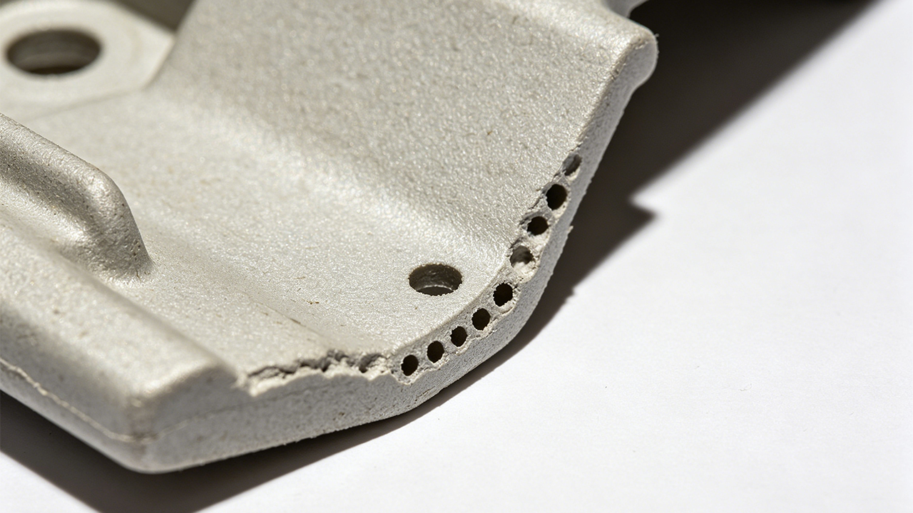
A short shot (also called an incomplete fill or non-fill defect) is a molding defect where the plastic melt does not fully fill the mold cavity, resulting in a part that is missing material in one or more areas. It appears as incomplete edges, voids in thin sections, or entire missing features on the molded part. The affected areas typically show a rough, frosted surface where the flow front stopped — quite different from the smooth, shiny appearance of properly filled sections.
What Does a Short Shot Look Like — and Why Does It Matter?
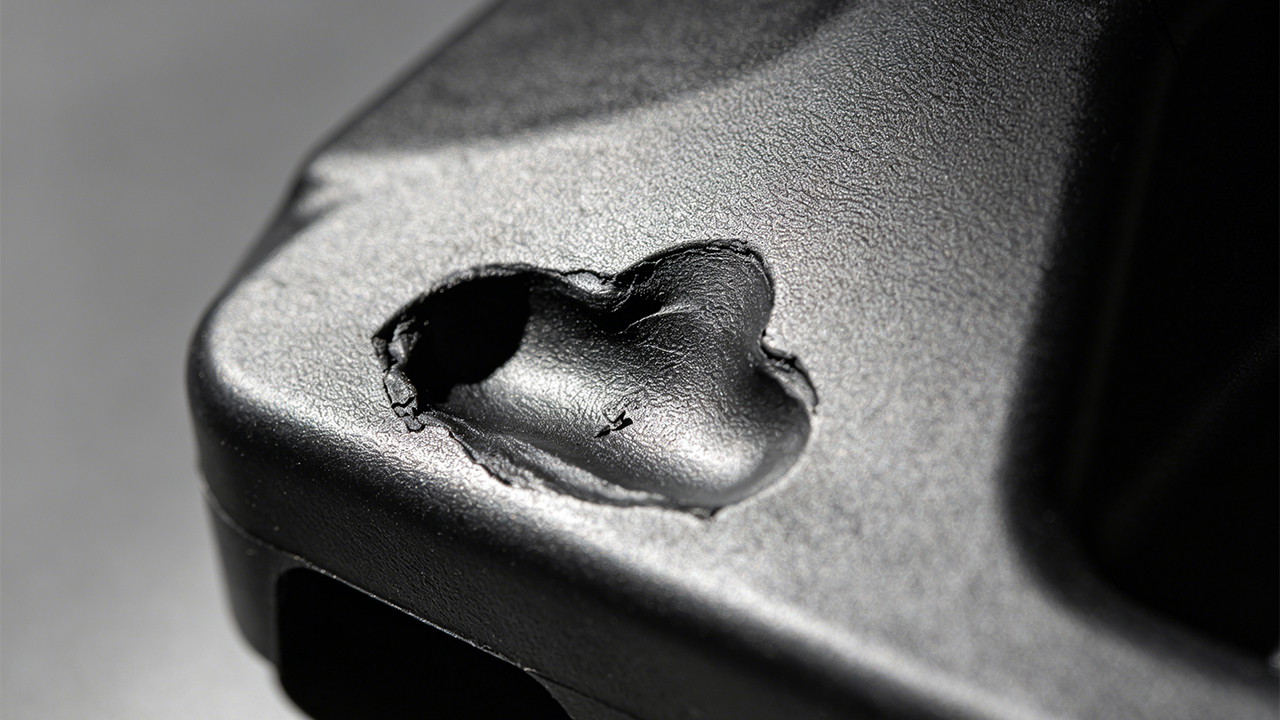
Visually, a short shot is obvious. Part of your component is simply not there. The flow front froze midway, leaving a rough, incomplete edge. Sometimes it’s a small cosmetic issue at a corner. Other times, entire functional features like mounting bosses or snap-fit arms are missing.
But here’s the thing — it’s not just a cosmetic problem.
A short shot means your part has reduced structural integrity. Wall sections that are thinner than designed, or incomplete rib structures, mean the part will likely fail under load. For consumer electronics or automotive components, that’s not a risk you can take.
From an engineering standpoint, understanding short shots is also important because they’re a signal. They tell you something in your system — process, material, or design — is out of balance. One of the most useful things I learned early in my manufacturing career was to treat defects as diagnostic tools, not just problems to patch. A short shot is the mold telling you that the plastic ran out of energy before it reached the end of the road.
Common Places Short Shots Appear
- Thin wall sections — plastic freezes off quickly in areas below ~1.0mm
- End-of-fill regions — farthest from the gate, where pressure is lowest
- Intricate ribs and bosses — complex geometry creates flow resistance
- Multi-cavity molds — when runner balance is off, some cavities fill late
The technical term for the fill pattern is “flow front.” When the flow front stalls, you get a short shot. Everything that influences how fast and how far that flow front moves — temperature, pressure, viscosity, venting — becomes part of the investigation.
Why Does an Injection Molding Machine Produce a Short Shot?
This is the question engineers ask first when a short shot shows up. And the honest answer is: there are several possible culprits, and they often overlap.
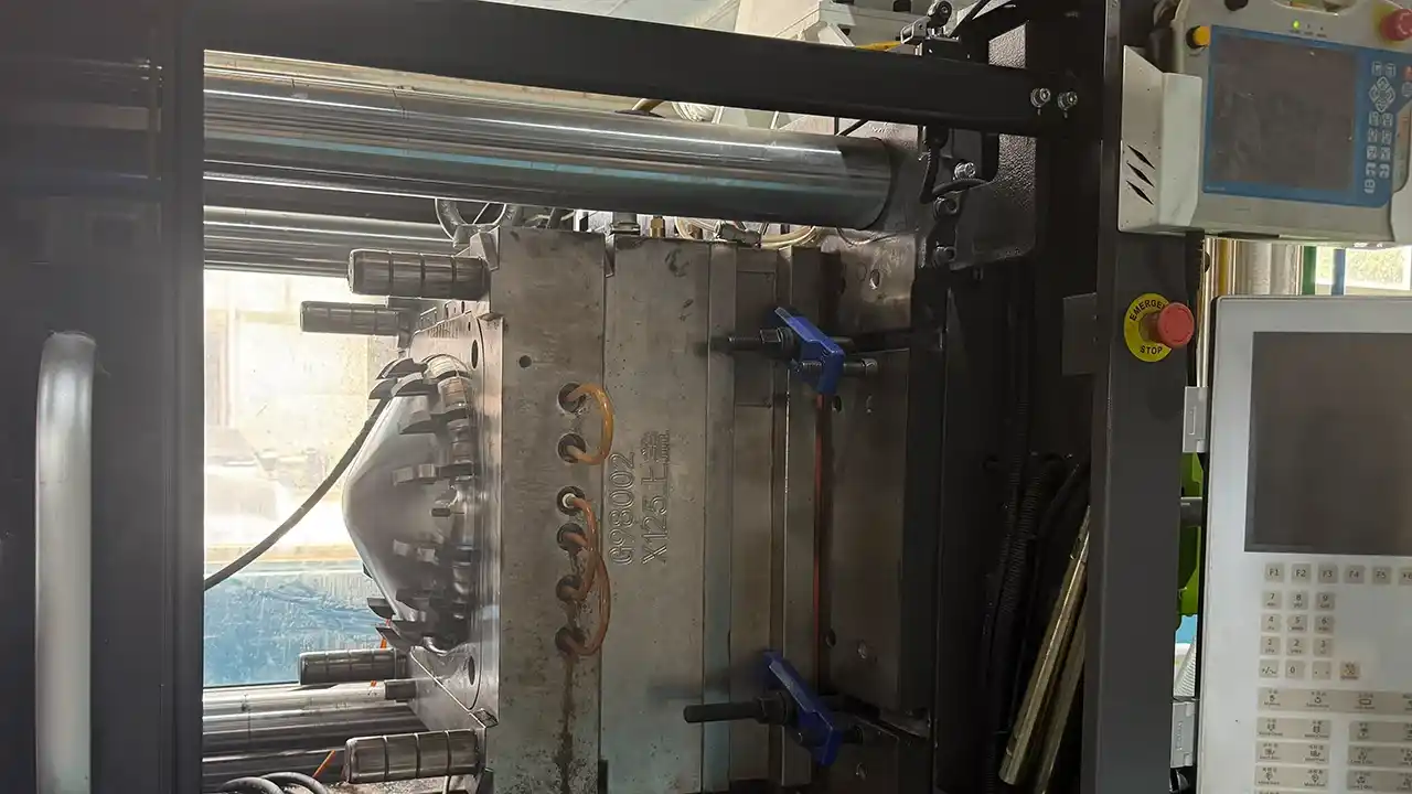
An injection molding machine produces a short shot when the melt cannot fill the cavity due to one or more of these factors: low injection pressure or speed, insufficient melt temperature, inadequate shot volume, a worn or malfunctioning non-return valve, or incorrect hold pressure settings. Machine-side issues are the first thing to check because they are the fastest to adjust — but they’re not always the root cause.
Breaking Down the Machine-Side Causes
Injection pressure and speed work together. Pressure pushes the melt through the runner and gate system; speed determines how fast the flow front moves before the material cools. If either is too low for the part geometry and material, you’ll get an incomplete fill.
Think of it like water flowing through a garden hose. If the pressure is too low, it barely dribbles out the end. The plastic is the same — it needs enough force to travel the full length of the flow path before it solidifies.
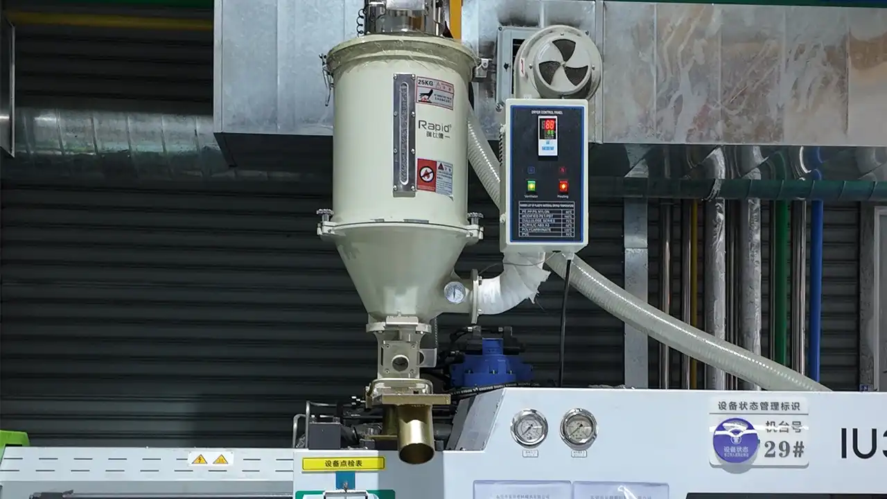
Температура плавления is another critical variable. Every thermoplastic has an optimal processing temperature range. Below that range, viscosity rises sharply, the material becomes sluggish, and it freezes off before reaching the far end of the cavity. ABS, for example, processed at 200°C instead of its recommended 230–250°C will behave like cold honey — technically flowing, but not nearly fast enough.
Shot volume — or the amount of plastic injected — is often overlooked. If the machine’s shot size is set too small (sometimes as a carry-over from running a different part), there simply isn’t enough material to fill the cavity. Always verify your shot volume setting is correct for the part weight plus runner/sprue system.
Non-return valve wear is a sneaky one. Over time, the check ring inside the injection unit can wear out, allowing the melt to backflow during injection. This reduces effective injection pressure and can cause inconsistent shot-to-shot filling — leading to random short shots that seem impossible to reproduce.
A Quick Diagnostic Thought
If you’re seeing intermittent short shots — sometimes complete, sometimes not — on the same machine without changing anything else, suspect the non-return valve first. Consistent short shots that never go away are more likely a design or venting issue.
How Do You Identify a Short Shot Defect in an Injection Molded Part?
Sometimes it’s obvious. Sometimes it’s subtle. Either way, identifying it accurately — and documenting where it occurs — is key to fixing it.
You can identify a short shot defect by visually inspecting the molded part for incomplete features, rough or frosted edges at the flow termination point, or areas where the surface finish degrades sharply. Measuring the part against its CAD nominal dimensions will confirm material is missing. In multi-cavity molds, comparing parts from different cavities reveals whether the issue is cavity-specific or global.
Practical Inspection Approach
A solid identification process doesn’t require fancy equipment — at least not at first. Here’s how I’d approach it:
Visual inspection first. Hold the part under good lighting and look at the edges, ribs, and thin features. Short shots typically appear as irregular, rough edges that don’t match the sharp, clean geometry of a properly filled area. The surface at the short shot location often looks milky or frosted because the material solidified rapidly without proper packing.
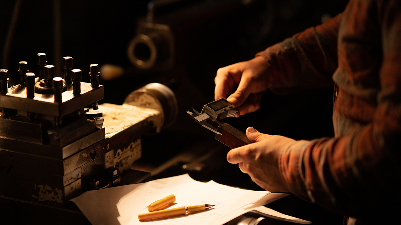
Dimensional checking. Use calipers or a CMM to check the suspect features against the part drawing. If a rib is specified at 15mm tall but measures 11mm, that’s not ambiguous — material is missing.
Progressive short shot testing. This is a technique I find incredibly useful for diagnosis. Intentionally reduce injection speed or pressure incrementally and examine the resulting parts. The filling pattern that emerges shows you exactly where the material struggles to reach — like watching the mold fill in slow motion. It’s one of the best ways to identify problem zones before production starts.
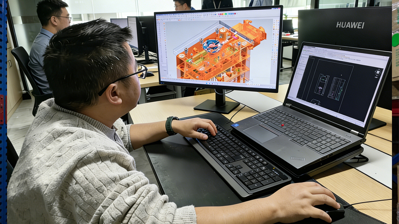
Mold flow analysis (before production). Tools like Moldflow or Moldex3D can simulate the filling pattern inside your mold before you cut a single piece of steel. At Dimud, our инженерное проектирование и конструирование пресс-форм team uses mold flow simulation as a standard step in the mold development process — catching potential short shot zones before they become physical problems.
Where to Document It
When you find a short shot, always mark its location on a part diagram or photo. Note which cavity it came from in a multi-cavity tool. This spatial data is gold for troubleshooting. A short shot in cavity 3 but not cavities 1 and 2 tells a completely different story than a short shot that appears in all four cavities.
How Does Mold Design Affect Short Shots in Injection Molding?
This is where things get interesting — and where the most durable fixes happen. Process adjustments can compensate for poor mold design to some extent, but they have limits. A fundamentally flawed mold will produce short shots no matter how well you tune the machine.
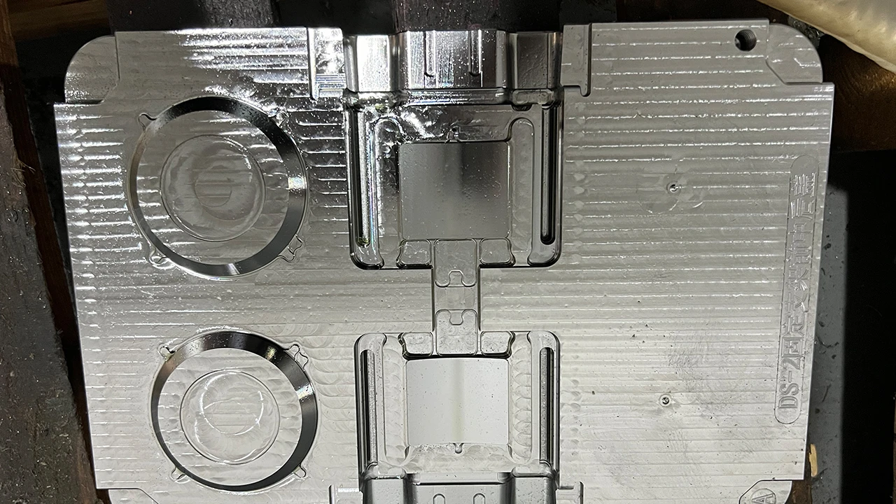
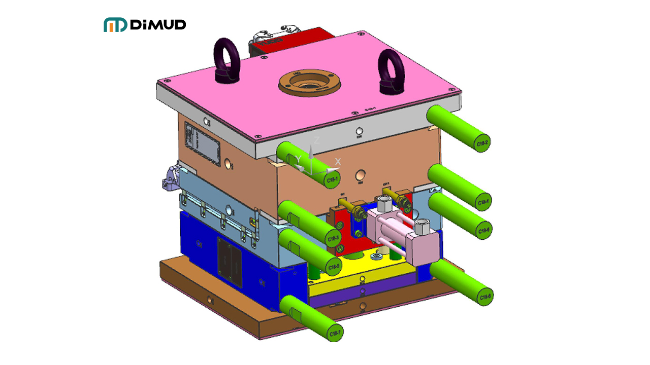
Mold design affects short shots primarily through gate size and location, runner system design, wall thickness uniformity, venting adequacy, and mold temperature control. An undersized gate increases flow resistance and drops pressure before the melt reaches the cavity. Poor venting traps air that physically blocks material flow. Unbalanced runners in multi-cavity molds create uneven filling, where some cavities short while others flash. Fixing these issues at the design stage is far more effective than compensating with process parameters.
Gate Design: The Most Common Design-Related Culprit
The gate is the entry point into the cavity. Get it wrong, and you’re fighting an uphill battle from the start.
Gate size directly controls how much resistance the melt faces entering the cavity. Too small, and the pressure drop across the gate is enormous — meaning by the time the melt is inside the cavity, it has lost much of the driving energy it needs to fill thin features or long flow paths.
Gate location determines the flow path the melt must travel. Ideally, the melt should flow from thick to thin, and gate placement should minimize the distance to the most challenging areas. Placing a gate at one end of a long, thin part and expecting the melt to travel the full length before freezing is asking for trouble.
Runner System: Resistance is the Enemy
Every curve, every diameter reduction, every unnecessary length in your runner system adds flow resistance and pressure drop. For производство прецизионных пресс-форм, runner cross-sections should be designed to minimize surface area-to-volume ratio (round runners are most efficient) and sized to the material’s flow properties.
In multi-cavity molds, a geometrically balanced runner system ensures all cavities fill simultaneously. When runners are unbalanced — meaning some cavities are further from the sprue — some cavities fill first and may flash while others are still short. Artificial balance through runner sizing can compensate for geometric imbalance, but it requires careful calculation.
Venting: The Invisible Problem
Here’s something that surprises many engineers when they first encounter it: air causes short shots too. As plastic fills the cavity, it needs somewhere to push the trapped air. If there’s no vent — or if vents are too small or clogged — that trapped air compresses and forms a physical barrier to the incoming melt.
You can sometimes spot this: short shots that occur consistently at the last point to fill (the end of the flow path) and show a slightly burned or discolored appearance at the incomplete edge. That discoloration is caused by diesel effect — the compressed air igniting as the plastic tries to push through it.
Proper vent placement at end-of-fill locations, with vent depths of approximately 0.02–0.05mm for most thermoplastics, solves this cleanly.
Факторы, влияющие на толщину стенки
Thin walls (below 1.0–1.5mm for most materials) freeze off very quickly. The melt must travel faster and at higher pressure to fill them before solidification. If your design has abrupt transitions from thick to thin sections, the thin section may freeze before the melt arrives.
This is exactly why early-stage Анализ технологичности matters so much. Reviewing wall thickness uniformity, identifying problematic transitions, and recommending design adjustments before the mold is built can eliminate entire categories of short shot risk — without any compromise to the part’s function or appearance.
How to Avoid Short Shots in Injection Molding — Process Parameter Adjustments?
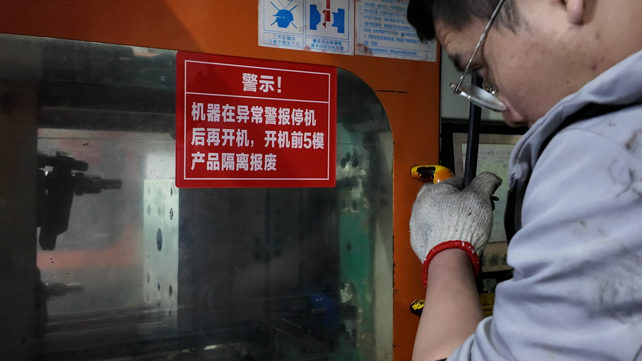
Even with good mold design, process parameters need to be dialed in correctly. This is where day-to-day troubleshooting happens.
To avoid short shots through process parameter adjustments: increase injection pressure and injection speed to overcome flow resistance; raise melt temperature within the material’s recommended range to reduce viscosity; increase mold temperature to slow surface solidification and extend fill time; verify and increase shot volume to ensure sufficient material; and adjust hold pressure to pack the cavity fully after the initial fill. Make one change at a time and document the effect on fill quality before proceeding.
Step-by-Step Process Adjustment Guide
Start with injection pressure. It’s the most direct lever. Increase it in increments of 5–10% and observe the result. If fill improves progressively, pressure was the limiting factor.
Then check injection speed. Speed and pressure interact. Higher speed reduces the time the melt spends in the cold mold, helping it reach thin sections before freezing. However, overly high speed can cause jetting or burning, so increase carefully — 10% increments are sensible.
Melt temperature. Check the material’s recommended processing temperature and confirm your actual barrel temperature settings match. Barrel temperature profiles should increase from the rear zone to the front zone. If all zones are set the same, the material may not be fully homogenized when it reaches the nozzle.
Mold temperature. A cold mold accelerates surface solidification, reducing effective fill time. Raising mold temperature (within the material’s requirements) slows freezing and extends how far the melt can travel. This is especially important for thin-walled parts and materials with high melt viscosity.
Shot size verification. Double-check your cushion setting. A cushion of 3–5 mm at the end of injection confirms that the screw didn’t bottom out during fill — meaning the shot size was adequate. If the cushion is zero, you ran out of material during the shot.
Hold pressure settings. Holding pressure isn’t about filling — it’s about packing. After the cavity is nominally filled, holding pressure compresses the melt slightly to compensate for volumetric shrinkage as it cools. Insufficient hold pressure can cause sink marks and dimensional short-fills near the gate area.
One Change at a Time
This sounds obvious, but it’s a discipline many engineers skip in the heat of troubleshooting: change one parameter at a time. If you raise temperature, speed, and pressure simultaneously and the short shot disappears, you have no idea which change fixed it. Next time the defect appears, you’ll be starting from scratch.
How Does Material Selection Affect Short Shots in Injection Molding?

Material choice isn’t just about mechanical properties. Flow behavior plays a major role in whether your part fills completely — or not.
Material selection affects short shots through melt flow index (MFI), viscosity, and thermal properties. High-viscosity materials like engineering-grade PC or glass-filled nylon flow less freely than general-purpose ABS or PP. For thin-walled or complex geometries, choosing a material with adequate flow characteristics — or a higher MFI grade — can significantly reduce the risk of incomplete fill without requiring higher pressures or temperatures.
Understanding Melt Flow Index (MFI)
MFI measures how easily a material flows under standardized conditions. A higher MFI means a lower-viscosity material that fills more easily. The tradeoff is often reduced mechanical strength or impact resistance — so the selection is always a balance.
For consumer electronics housings and similar parts, PC/ABS blends offer a practical middle ground: better flow than pure PC and better strength than pure ABS. This is precisely the kind of material trade-off that should be evaluated during the design and DFM stage — not after you’re already in production and chasing short shots.
Material Moisture Content
This one catches people off guard. Hygroscopic materials — nylon (PA), PET, and PC—absorb moisture from the air. If they’re not dried properly before molding, that moisture turns to steam inside the barrel. Steam increases viscosity irregularly and can cause inconsistent filling. The fix is straightforward: dry your material according to manufacturer specifications before processing. For PA66, that’s typically 80°C for 4–8 hours. For PC, 120°C for 4–6 hours.
Наш сайт materials resource page covers the key plastic materials we work with and their processing requirements — useful reference if you’re evaluating material options for a new project.
Can Short Shots in Injection Molding Be Prevented at the Design Stage?
Yes. And this is where the biggest gains happen — because catching a potential short shot before the mold is built costs almost nothing compared to modifying tooling or scrapping production runs.
Short shots can largely be prevented during the design stage through three key practices: Design for Manufacturability (DFM) review, mold flow simulation, and rapid prototyping. DFM identifies wall thickness issues, thin ribs, and unfavorable gate locations before tooling begins. Mold flow simulation predicts fill patterns, weld lines, and air trap locations. Prototype validation confirms that the design behaves as expected under real process conditions. Together, these steps eliminate the vast majority of short-shot risk before a single part is produced.
Why DFM Is the Most Cost-Effective Prevention Tool
I’ve said this before and I’ll keep saying it: the earlier you catch a problem, the cheaper it is to fix. A DFM review that recommends increasing a 0.8 mm wall to 1.2 mm costs nothing to implement in CAD. Modifying a steel mold after it’s been machined can cost thousands of dollars and delay your launch by weeks.
At Dimud, our product design and DFM service starts before the mold is designed. We review part geometry, wall thickness, draft angles, and gate locations and identify features that are likely to cause short shots or other defects. For clients who come to us with early-stage designs, this process can save significant time and cost downstream.
Mold Flow Simulation: Seeing the Future
Modern mold flow analysis software can simulate exactly how plastic will fill a cavity, predict where the last point of fill will be, identify air trap locations, and estimate the required injection pressure. It’s not perfect — real-world conditions always add variability — but it reduces the number of surprises dramatically.
If your current mold supplier doesn’t run flow analysis as a standard step, that’s worth noting.
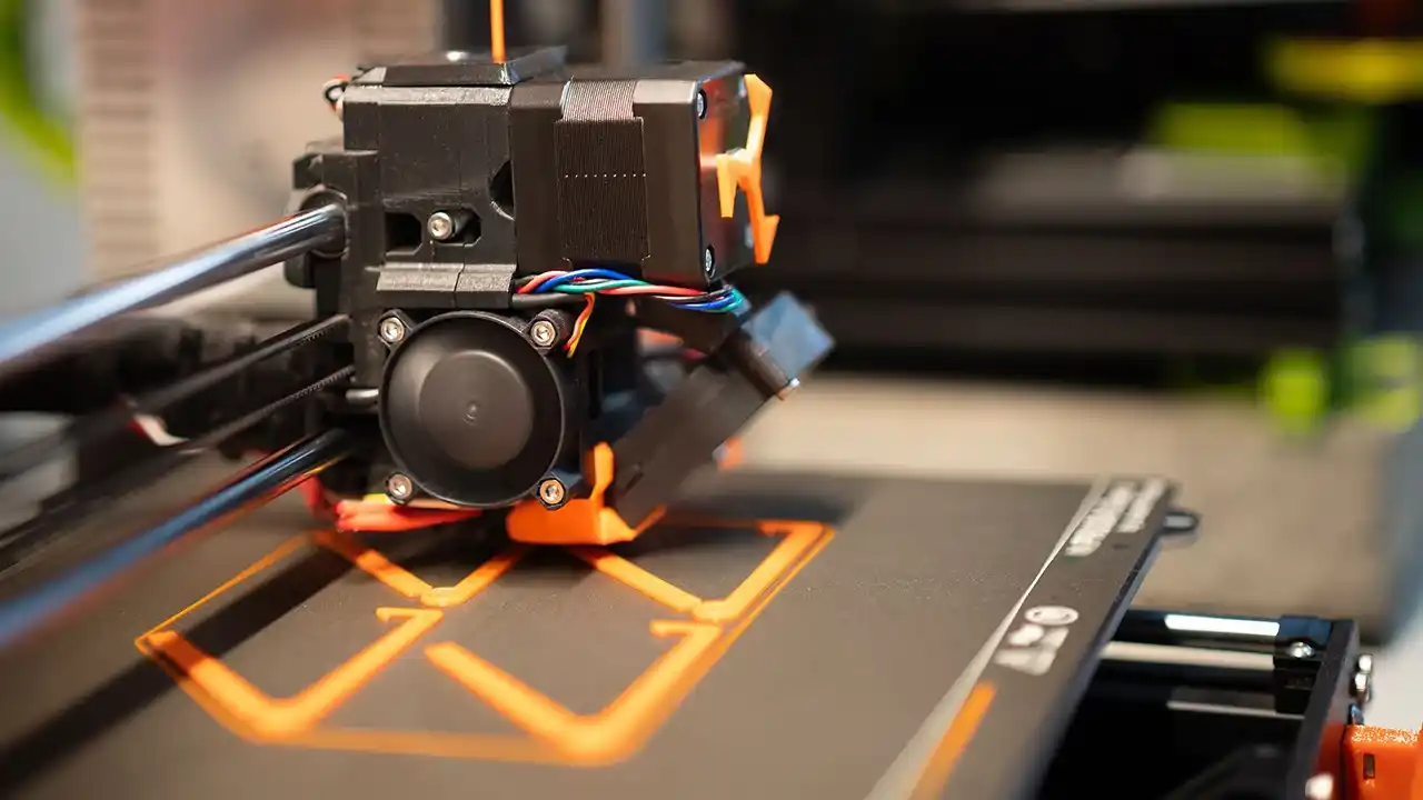
Rapid Prototyping for Design Validation
Before committing to production tooling, создание прототипа through 3D printing or rapid tooling lets you validate the design physically. While 3D-printed prototypes don’t replicate injection molding flow behavior exactly, they confirm fit, assembly, and function. Rapid tooling — low-cost soft molds made in shorter lead times — can validate both the design and the basic molding process before investing in full production tooling.
Заключение
Short shots are frustrating. But they’re rarely mysterious. Most of them trace back to something predictable — a gate that’s too small, a vent that’s missing, a wall that’s too thin, or a machine setting that drifted. The key is knowing where to look and catching the problem as early as possible.
The best time to prevent a short shot is during DFM review. The second-best time is during mold flow simulation. By the time you’re adjusting process parameters on the production floor, you’re already spending more money than you needed to. Build prevention into the front of your development process — and short shots become the rare exception, not the frustrating routine.
Have a project where short shots have been a recurring headache? Dimud’s engineering team works with product developers and manufacturers to identify root causes and build defect-resistant production processes. Свяжитесь с нами to discuss your project.