Sumitomo Electric Industries Ltd. has developed and produced high-voltage wiring harnesses and connectors for electric transmission systems, which have been used in many hybrid electric vehicles (HEVs). In the past 25 years, hybrid vehicles have been actively developing to prevent global warming caused by CO2 emissions. The development of electric vehicles (EVs) that do not require internal combustion engines is also accelerating. The electric transmission system used in EVs mainly consists of high-voltage batteries, inverters, and motors. This article introduces the products we have developed for hybrid vehicles, which are also applicable to electric vehicles. These products include pipeline shielded wire harnesses for aluminum wires between high-voltage batteries and inverters, as well as power cords and direct connectors for connecting inverters to motors.
01 Introduction
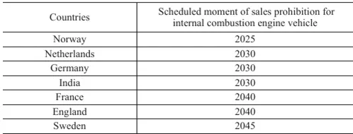
In the past two decades, the development of hybrid electric vehicles (HEVs) and electric vehicles (EVs) has accelerated in order to improve fuel efficiency and reduce CO2 emissions to prevent global warming and depletion of fossil fuels. Especially, hybrid vehicles are rapidly becoming popular because existing gas stations can be used for refueling. The recently announced bans on the sale of internal combustion engine vehicles by various countries are shown in Table 1, with tightened CO2 emission regulations. Therefore, the sales of electric vehicles have shown a growth trend as shown in Figure 1. At present, it is expected that the ratio of hybrid vehicles to electric vehicles will continue to remain high. However, the development of non internal combustion engine electric vehicles is accelerating. Therefore, with the development of batteries and charging technology, it is expected that the proportion of electric vehicles in electric vehicle sales will increase.
The electric transmission system of hybrid or electric vehicles mainly consists of high-voltage batteries and electric motors. They are connected together through high-voltage wiring harnesses to complete power transmission. Sumitomo Electric Industries Co., Ltd. has been producing high-voltage wire harnesses for nearly 20 years. In addition, in the wave of electrification, Sumitomo Electric is promoting the development of high-voltage wiring harnesses to increase the motor power of hybrid vehicles, reduce weight to improve fuel efficiency, and further apply them to electric vehicles.
Table 1: Prohibition Policy for Internal Combustion Engine Vehicles
In this article, we describe the structure and characteristics of the following components developed for hybrid electric vehicles (HEVs) and also applicable to electric vehicles (EVs): power cables, direct connectors, and conduit shielding harnesses for aluminum wires.
As shown in Figure 1: Prediction of Sales Ratio between Internal Combustion Engine Vehicles and Electric Vehicles
02 Electric transmission system and high-voltage wiring harness
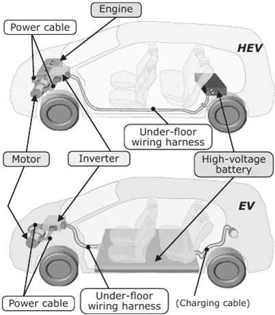
The power transmission system of hybrid or electric vehicles mainly consists of high-voltage batteries, inverters, and electric motors. As shown in Figure 2, they are connected to each other through a high-voltage wire harness. The high-voltage harness that connects the high-voltage battery and inverter is called the underfloor harness, and its wire length is relatively long. The high-voltage wire harness connecting the inverter and the motor is called a power cable, and its length is relatively short. Both types of high-voltage wiring harnesses require shielding performance to ensure that electromagnetic noise does not affect surrounding electronic devices.
Noise will not affect the surrounding electronic devices and signal lines. The underfloor harness is arranged under the car floor, so it is very important to have a protector to protect the wires from external damage (such as stone strikes). The protector adopts resin protector and metal tube.
Recently, due to the decreasing distance between the frequency converter and the motor, the length of the power cord has also shown a trend of shortening. Sumitomo Electric has developed two products based on this trend. One type is miniaturized and lightweight power cables. The length of power cables has been reduced from about 100 centimeters to about 10 centimeters. Another type is a direct connector, which uses a high-voltage connector to directly connect the frequency converter and motor. The use of these two products depends on the characteristics of the vehicle.
As shown in Figure 2: Electric Transmission System of HEV and Electric Vehicle
03 Hybrid electric vehicle specific products suitable for electric vehicles
In this section, we will introduce developed HEV products that are also applicable to electric vehicles.
1 ► Pipeline shielding harness and positive and negative (PN) connectors
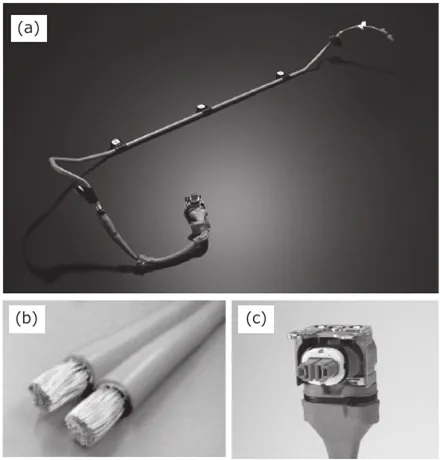
As mentioned earlier, the protection of underfloor harnesses is crucial. Sumitomo Electric has been using aluminum tubes instead of resin protectors as protective materials to produce tube shielded wire harnesses since 2005. (1) One of the characteristics of tube shielded wiring harness is that the aluminum tube serves both protective and shielding purposes. In addition, it has good heat resistance and thermal conductivity, and is suitable for various layout shapes of tube shielded wire harnesses using three-dimensional bending technology.
For traditional shielded wire harnesses, the wires inserted through the pipeline are copper wires. However, as the power of hybrid vehicles increases, a larger current is required, resulting in an increase in the cross-sectional area of the wires. Therefore, the increase in wire weight has become a problem. From the perspective of improving fuel efficiency, it is necessary to reduce the weight of the wires. To address these issues, we have developed an aluminum wire. Aluminum wires used for shielding wire harnesses should have both anti vibration flexibility and good conductivity. We achieved weight reduction using a new type of aluminum material that meets these two requirements (Figure 1 (a), (b)).
Figure 1: Tube shielded wiring harness and PN connector
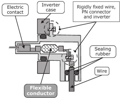
On the other hand, another developed product in this pipeline shielding harness is a high-voltage connector called a PN connector, used on the inverter side (Figure 1 (c)). Due to the high current passing through, the pipeline shielding harness uses thick wires with a large cross-sectional area. When the vehicle is in motion, the thick wires installed in the vehicle will vibrate with the vibration of the vehicle. The vibration of this type of wire acts on the connector through the thick wire, which may cause wear on the electrical contacts of the connector and potentially result in terminal heating. In order to suppress this vibration, it is necessary to firmly fix the wires, connectors, and inverters to each other. However, this may lead to wear on the electrical contacts of the connector, as the expansion and contraction of the connector components caused by temperature changes may not be absorbed.
Figure 3 shows the PN connector developed considering these factors. As shown in Figure 3, although the PN connector has a firmly fixed structure, the flexible conductor absorbs the component size changes caused by thermal expansion and contraction. This structure improves the reliability of the PN connector.
As shown in Figure 3: Absorption of PN connector size changes
Due to its one click assembly structure instead of traditional bolt structure, this connector significantly improves operational convenience when connecting pipeline shielding harnesses to inverters.
2 ► Power cables
As mentioned earlier, the distance between the inverter and the motor is becoming shorter and shorter. This section describes the power cables we have developed to address this trend.
The power cable of the development target vehicle connects the inverter and two three-phase alternating current (AC) motors (one for driving the vehicle and the other for generating electricity). The power cable consists of three thick wires for each motor (a total of six thick wires), connected at both ends to the high-voltage connectors of the inverter and motor, as well as a shielding layer for shielding electromagnetic noise. In order to apply this power cable to the short distance between the inverter and the motor, it is necessary to reduce its size and weight.
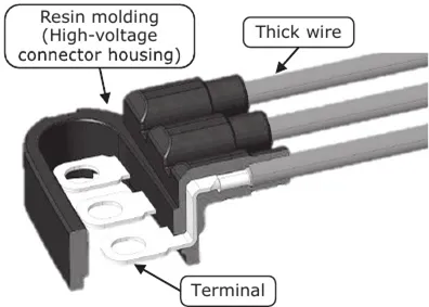
In traditional high-voltage connectors, resin molded shells are assembled at both ends of three thick wires and sealed. Traditional power cables use two sets of such devices. In order to reduce the size of this power cable, we adopted the six phase integrated molding technology (Figure 4), in which six wires are inserted and molded at once. Therefore, the use of rubber seals is avoided, and the two sets of power cables are integrated into one, achieving miniaturization.
Figure 4: Schematic diagram of the concept of six phase integral molding technology
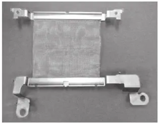
In the shielding layer of traditional power cables, the wires are wrapped in a tubular braided shield. Therefore, due to the terminal connections of the shielding layer, the size reduction of power cables is limited. This time, we utilized the advantage of being suitable for short distances by using cloth like shielding materials. As a result, we achieved a reduction in size and weight of the new power cable (photo 2).
Photo 2: Copper Braided Shielding
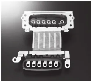
These measures of reducing size and weight have made it possible to develop the power cable shown in photo 3, which can be installed in narrow and limited spaces.
Photo 3: Appearance of power cables
3 ► Direct connector
In this section, we describe a direct connector that uses a high-voltage connector to directly connect the inverter and motor.
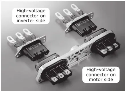
With the trend of vehicle layout, the inverter is directly installed above the motor. In order to improve the work efficiency of automobile assembly plants, there has always been a demand for a technology that can connect the inverter and the motor while installing the inverter above the motor without using cables. As a solution, we have developed direct connectors, in which the high-voltage connectors are integrated into the inverter and motor respectively (Photo 4).
As shown in Figure 4: Appearance of direct connector
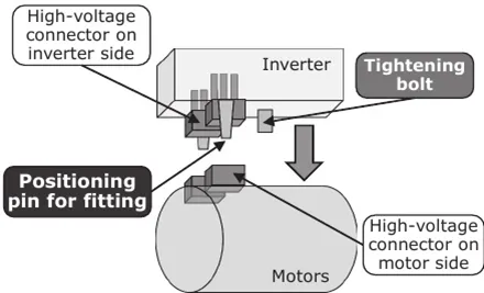
In order to connect the inverter and motor while installing them above the motor, high-precision alignment is required. However, it is difficult to install heavy-duty inverters while making fine adjustments. Therefore, the high-voltage connectors of the inverter and motor should be able to pair with each other based on rough alignment. In response to this requirement, a two-step guidance structure was adopted. The first step is the initial stage of connector pairing when the inverter moves towards the motor. We have set positioning pins on the inverter housing, adjusted the shape of the pins, and set appropriate guiding margins to achieve optimal positioning while avoiding interference from high-voltage connectors (Figure 5).
As shown in Figure 5: Installation operation of inverter and motor (first step)
The second step is the stage before the start of terminal bonding. At this stage, further high-precision alignment is required for terminal bonding. To meet this requirement, guide components are installed on the high-voltage connector on the motor side. Meanwhile, the high-voltage connector on the inverter side adopts a floating structure. These measures make self alignment possible. In addition, flexible conductors are applied inside the high-voltage connectors on the inverter side to absorb the gaps caused by the bolt terminal connection positions inside the inverter due to self alignment (Figure 6). These measures enable two high-voltage connectors to be paired with one action and one bolt tightening. As a result, the operability of installing inverters and pairing high-voltage connectors has been greatly improved.
As shown in Figure 6: High voltage connector fitting (second step)
04 Design Description
All products reported in this article were developed with the application of electric vehicles in mind. In addition, they also help reduce the size and weight of products, improve the reliability and processability of automotive assembly plants. They have been installed on mass-produced hybrid vehicles.
Special statement: This article is translated from https://www.elecfans.com/d/6328569.html .If there is any infringement, please contact us for deletion. Thank you.
To find products and services more accurately, please try entering keywords for search.
For more product and service content, please contact us and send an email to sales@dimud.com.
We sincerely look forward to connecting with you!


